Corvette Repair and Paint Tech Session for The Corvette Society! I would like to thank Gerard, Marc & George for hosting a great educational tech session. I would also like to thank Billy G who helped set up the event. Gerard and I have been friends for close to 30 years. He prepared a tech session covering all of the below topics.
I thank all of our members plus members of the VCCA who attended this event in 20-degree weather!
Introduction
Marc Stark – Owner Operator
Gerardo Gonzalez – Shop Foreman
Our Services Classic Car body and paint restoration
HOW DRIVEN CORVETTES AND THE NCRS CAN CO-EXIST B Y J O H N H I N C K L E
In the September issue, we went into the design and operating characteristics of the Corvette cooling system and discussed some diagnostic and troubleshooting techniques for those of you who have various cooling problems. Most cooling problems in older Corvettes, especially those with aged original radiators or those that have had the original radiator replaced with one that was less costly (and has less heat-rejection capability), simply don’t have adequate cooling capacity to dissipate the heat carried to it by the coolant. There’s only one cure for that problem – a new radiator with at least the same heat-rejection capability as the original
The objective of this article is to take you through a radiator replacement and to share some tips and techniques that will simplify the job and ensure a reliable and leak-free installation. The car in the photos is a ‘67 327/300 with a relatively new “look-alike” copper/brass replacement radiator which was designed to look like the original Harrison aluminum radiator, but had far less cooling capacity. Diagnostics and I.R. gun studies verified that the engine was running at 195°-200° at freeway speeds, and would creep up to 210°-220° in slow traffic on an 85° day, with correct shrouding and a new fan clutch. The “while it’s apart” syndrome took hold, as it always does, so we replaced the radiator hoses, heater hoses and clamps as well, with judging-correct parts. The choice of a radiator was simple – a DeWitt’s reproduction of the original GM #3155316 Harrison stacked-plate aluminum radiator, dated and detailed to pass NCRS judging. Don’t even bother to start this project with anything that has less cooling capacity than the original radiator, or you’ll be doing it again later – once is enough
DRAINING COOLANT: Start by draining the old coolant. Plastic gallon milk jugs (you’ll need four) make good storage containers until you can take them to your local recycling center for proper disposal. Don’t stop at the petcock drain at the bottom of the radiator – that will only drain about two-thirds of the coolant. Remove the drain plug on each side of the block, centered just above the pan rail, to drain the water jackets around the cylinder walls. You need to remove both of them, as they aren’t cross-connected, and they hold a lot of stagnant coolant. Use a six-point socket to remove them, and when you replace them, use a bit of anti-seize on the threads so they’re easy to remove next time (as we discussed in September, you should drain and replace your coolant every two years so the inhibitor package continues to protect your radiator from corrosion, its worst enemy). Don’t be surprised if nothing comes out when you remove each plug – that area collects lots of corrosion and crud, and you may need to poke up into the hole with an awl or screwdriver to loosen the accumulated crud to break it loose. Be sure and have a pan handy, as the coolant will pour out once the opening is clear.
FAN AND CLUTCH REMOVAL: Next, remove the fan and clutch as a unit (leave the fan attached to the clutch). It’s much easier to loosen the bolts that attach the clutch hub to the water pump (through the water pump pulley) if you leave the fan belt in place until you’ve loosened the four bolts, then remove the fan belt, then remove the four bolts and pull the fan/clutch assembly. At this point you can decide if the fan and clutch need to come apart for cleaning/detailing.
RADIATOR HOSES: The radiator hoses come off next. If you have the tower-style clamps, loosen the screw at least half its length, place a 3/8” or 7/16” deep-well socket over the screw so it bottoms out on the “tower” of the clamp, and give it a couple of light raps with a hammer to expand the clamp and move it out of the way. If you’re careful here, you may be able to re-use the clamp (more on tower clamps later). The easiest way to remove the old radiator hoses is to slice them lengthwise with a box knife and “peel” the two edges of the cut away from the neck (assuming you’re replacing the hoses). Remove the thermostat housing and thermostat, remove the old gasket, and clean up the mating surfaces and the offset surface where the thermostat seats. We’ll put the thermostat housing back on with a new gasket later on while we’re refilling the cooling system.
HEATER HOSES AND EXPANSION TANK: Next on the list are the heater hoses and the expansion tank (if you have one). This system is best removed as a unit (rather than one piece at a time) so you can lay it out on the floor and cut all the new replacement hoses to the exact length as the old ones before you reinstall everything over the fender. Tip: Don’t go nuts trying to remove (or install) the original round wire “Corbin” clamps with a pair of pliers – those clamps will fight your pliers every inch of the way. Go to your auto parts store and get a pair of spring-loaded ratcheting Corbin clamp pliers with swiveling jaws – they grab the ends of the round wire securely and make the job a piece of cake. Caution: Be sure and use the “slice and peel” technique to remove the old heater hoses from the heater core pipes, and do it gently. If you just pull or twist them off, chances are excellent that you’ll crack the solder joints at the other end of the pipes and end up with a heater core leak, which can cost you carpets as well as the grief of replacing the heater core. The same caution applies for the 3⁄4” hose that connects to the lower outlet from the expansion tank. It’s aluminum, and you don’t want to damage the pipe or its joint to the tank. Two more screws and two clamps and the expansion tank and its inlet hose from the radiator are out, and the whole system can come out and park on the floor. Now you can think about cleaning up the tank and the two retaining straps.
FAN SHROUD: Now the fun begins – some shrouds can be removed without trauma, but most can’t (especially C3s). My original ’67 327/300 fiberglass shroud is relatively fragile, but doesn’t have to be completely removed – just pulled back and out of the way, at a weird angle, to provide clearance to pull the radiator out vertically (you can always tell the ones Bubba removed – they’re broken and have pop-rivet or Bondo repairs and/or missing chunks). The ’67 shroud is attached with four bolts from the front side of the radiator support, through holes in the support, into U-nuts on the edges of the shroud, and a bolt-on bracket at the top. Small hands and skinny arms (neither of which I have) are helpful to get to the bolts, and both horns have to be either removed or loosened and rotated out of the way, as the horn brackets block access to the lower two shroud bolts. Just work slowly, be patient, take a beer break occasionally, and you’ll be able to get the shroud out of the way without damaging it.
RADIATOR: The small-block radiator has two pins on the bottom plate with rubber donut isolators on them that nest in holes in brackets on the bottom of the radiator support, and a center retaining bracket and rubber isolator at the top with two bolts through the top of the radiator support. Big-blocks (and most C3s) have welded saddles with rubber cushions at the bottom and bolt-on saddles with rubber cushions at the top. Remove the upper attachments, set the pieces aside, and you’re ready to remove the radiator. A helper is recommended, as the radiator must come up vertically without hanging up on the radiator support or shroud, and it’s pretty awkward (and heavy, if it’s a copper/brass radiator), and still has some coolant in it that will dribble as you maneuver it out and set it aside. Now you can get a good look at the bottom of the radiator support and check it for cracks or corrosion damage and paint it if necessary.
This is also the time to inspect the condition of any foam or flap rubber seals you may have (or which may be missing) between the shroud and radiator, radiator and support, or support and hood, and replace them. If you need them, “Dr. Rebuild” has the most comprehensive selection of replacement seals, made from the correct materials to the original drawings. Not t to worry – it’s all downhill from here.
RADIATOR: Now just reverse the process, using new rubber isolators and cushions, with cleaned-up or freshlypainted mounting brackets (the new DeWitt’s radiator is a thing of beauty, and will make old mounting hardware look pretty ugly). The new radiator will most likely be lighter than the old one, so it’s not as awkward to maneuver into place, but be very careful not to snag its plates and fins on anything as you position it. You’ll also note that it has an aluminum drain petcock instead of brass, to eliminate a possible source of galvanic corrosion from dissimilar metals. Once it’s secure, it’s fan shroud time again.
FAN SHROUD: Carefully maneuver the fan shroud into position against the radiator support, being careful not to force it or break it. If it won’t move, find out why and clear the problem before proceeding. Be particularly careful in the area around the neck for the upper radiator hose – the shroud is very fragile there. Reinstall the retaining bolts through the radiator support and upper radiator retaining bracket, reposition and secure the horns, and the major stuff is done.
FAN AND CLUTCH: Positioning the fan/clutch assembly and water pump pulley over the water pump hub and getting the three-piece sandwich of holes for the fine-thread bolts aligned so you can start the bolts into the hub “blind” can be time-consuming and frustrating, as you don’t have much room to work in. Tip: This task is simplified by using a stud (cut the head off a fine-thread 5/16”-24 bolt so you have a 5/8”-long stud – any longer, and you won’t be able to remove it). Insert the stud into one of the bolt holes in the hub, install the pulley over the stud and center pilot, followed by the fan clutch hub, and start three of the four bolts (the stud aligns all three holes in the “sandwich”); then remove the stud and replace with the fourth bolt, and tighten the four bolts.
RADIATOR HOSES: Make up a 50- 50 mix of water and anti-freeze in a cup, and brush it on the inside of the ends of the hoses just before you install them – makes them easier to position, and avoids putting undue stress on the radiator’s inlet and outlet necks (slide your clamps over the ends of the hoses first). Once the hoses are properly oriented, tighten the clamps. Position the thermostat housing (and clamp) at the engine end of the upper hose and trial-fit it to the intake so the bolt holes line up, tighten the clamp, and push it aside for now (we’re going to fill the system through the thermostat hole in the intake later).
A NOTE ABOUT TOWER CLAMPS: Original production tower clamps were made by Wittek, and were of very high quality. Wittek went out of business many years ago, and someone is reproducing “correct” dated Wittek tower clamps, which are not manufactured with the same materials or to the same standards as the originals, although they “judge well.” I have not had good luck with these reproductions, and prefer to use genuine NOS ($$) Wittek tower clamps; if originality is not an issue for you, screw-type worm clamps work just fine.
HEATER HOSES AND EXPANSION TANK: Using the old system you laid out on the floor as a unit as a pattern, cut your new heater and expansion tank hoses to the correct length, and sub-assemble the new system out of the car. I used all new Corbin clamps, and here again, the Corbin clamp pliers are well worth their cost. If you’re using reproduction hoses and are into judging, rotate the hoses into position so the markings and ribs will show when the system is installed. The 5/8” hose goes from the nipple on the intake manifold to the lower heater core pipe, and the 3⁄4” hose goes from the nipple on the water pump to the expansion tank tee to the upper heater core pipe. Take the sub-assembled system to the car, install the expansion tank straps, and make the connections to the nipples at the engine end and to the heater core pipes. Using the 50-50 mix of water and anti-freeze you made up earlier for the radiator hoses, apply some inside the heater core end of both heater hoses so they slide on without much pressure. As I noted earlier during disassembly, you don’t want to apply undue force on those two core pipes. Tip: When you cut the hoses to length during sub-assembly and if you need to trim them a bit when you make the final connections, the Craftsman “Handi-Cut” is a terrific tool – it cuts them easily, squarely and neatly with hardly any effort at all. Using a box knife to cut hoses in awkward areas can inflict some really nasty injuries if you’re not careful.
COOLANT FILL: Get two gallons of name-brand ethylene glycol-based antifreeze. I prefer the conventional “green stuff” (Zerex, Prestone, etc.), although you can use the new Dexcool-type “red stuff” if you like. You should thoroughly flush and back-flush the cooling system if you plan on using the Dexcool-type coolant to get rid of traces of the old “green” anti-freeze, as the inorganic salts deposited by the “green” coolant reduces the effectiveness of the long-life organic inhibitor package in the Dexcool coolant, and you’ll need to change either one every two years anyway. The “long-life” feature only works in brand-new cooling systems (you’ll find that disclaimer in small print on the Dexcool-type coolants). I don’t recommend using the propylene glycol-based “environmentally-friendly” coolants (“Sierra”, etc.), as OEM tests have shown they have about 10% less heat-transfer efficiency than ethylene glycol-based conventional coolants at the same concentration, and you don’t need 10% less cooling capacity in a Corvette. While you’re out, get two gallons of distilled water at the grocery store to mix with it; tap or well water contains dissolved minerals that will tend to reduce the effectiveness of the coolant’s anti-corrosion inhibitor package and increases the rate of accumulation of scale deposits in the cooling system.
Before you start, make sure the radiator drain petcock is closed tight, the two block drain plugs are in place, and make sure you have the correct RC- 26 expansion tank cap (it’s unique to the aluminum radiator cooling system to prevent galvanic corrosion due to dissimilar metals). It’s also a good idea to take the cap to your auto parts store when you get your anti-freeze and have them check it on their cap tester to make sure it seals and holds it rated 15# pressure. If it won’t seal properly or hold its rated pressure, you’ll lose the boil over protection it provides, especially during “heat-soak” after engine shutdown. While you’re there, get one of the plastic radiator fill funnels and drill a bunch of 1⁄4” holes near the small end (see photo) when you get home. I’d also recommend buying a Robertshaw #330-180 “balanced flow” thermostat (180° rating); it’s much more accurate than the generic types, and won’t ever fail closed. Now that we have all our materials, let’s fill the cooling system – this method will avoid creating any air pockets in the system, and won’t require “burping” the system to get rid of them. We’ll do the initial fill through the thermostat opening in the intake manifold, install the thermostat and housing, then top it off through the expansion tank fill opening. Place the funnel with the drilled-out end in the thermostat opening. The end of the funnel will bottom out in the coolant passage, and it will stand up straight by itself. Carefully pour the first gallon of anti-freeze into the funnel, and follow with the first gallon of distilled water. Then half-fill the empty water jug or empty anti-freeze container with anti-freeze from the second gallon, and fill it up the rest of the way with distilled water. Pour this 50-50 mix into the funnel, watching as the level rises in the bottom of the funnel. When it stabilizes near the top of the opening, stop pouring, install the thermostat, gasket, and housing, and torque the housing bolts. Tip: Fel-Pro makes a great molded plastic gasket with a molded-in silicone seal bead (#35562T), and GM has a similar one (GM #10105135). Neither requires any sealer. Now continue filling the system with a 50-50 mix at the expansion tank until the tank is half full, and just place the cap on the neck (don’t turn it down tight – the system must be open to purge any air).Check for any leaks at the hose connections and drains – if OK, start the engine and let it run until the thermostat opens (the upper hose will get hot in a hurry when it opens). Then let it idle for another five minutes or so, and check the level in the expansion tank occasionally as the system purges any air while you monitor the hoses for leaks and correct them. Add more 50- 50 mix as necessary to keep the tank at least half full while it purges. When the level stabilizes, shut off the engine and turn the cap on tight – you’re done! Check the level in the tank the next morning when the system has cooled down, and add 50-50 mix if necessary to the half-full mark.
THE BOTTOM LINE: Now you can take it out and drive it, and observe the temperature gauge, comparing the readings under different conditions to what you were seeing before with the old radiator. You’ll be amazed at the difference! Mine simply sits at 180° all the time, whether on the freeway, in traffic in town, or just sitting at idle in the driveway – it never varies. With your Corvette’s original cooling capacity and extra cooling margin restored, you can watch the scenery as you drive instead of the temperature gauge, and not worry about engine temperature at all any more. Maintenance? Just change the coolant every two years, and your new radiator will last longer than you will.
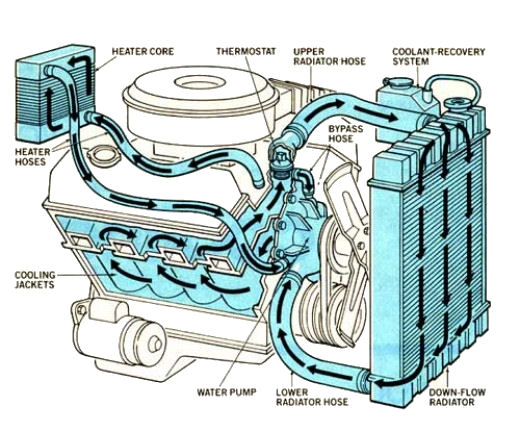
This illustrates a typical big block 396/427/454 cooling system. All small block systems are essentially the same with the exception of the bypass hose.
Heater Core
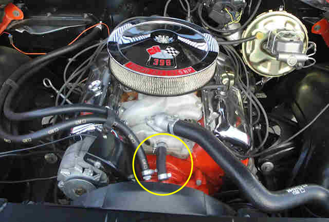
One ‘trick’ some people like to do is removing the heater to save weight and running a hose from the outlet fitting (seen here on the intake manifold) to the inlet fitting on the water pump. While this may save a few pounds of weight it reduces the cooling system capacity and leaves you without a defroster; something to think about in a tradeoff. Typically water does not circulate through the heater core unless the heater is turned on. Having this extra capacity can also help cool an engine on hot days by the very nature of more coolant and (if you can stand the heat), you can turn your heater on to circulate more coolant throughout your system and take advantage of the system’s coolant capacity.
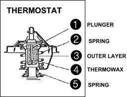
Thermostat
A thermostat allows the engine to circulate its coolant internally until the designated temperature of the thermostat is reached and allows coolant to flow into the top of the radiator. A thermostat is not designed to cool an engine but rather to allow the engine to come up to operating temperature. Thermostats come in various degrees of operation; 160°, 180° and 192°/195°. This is the temperature the thermostat begins to open.
A small cylinder is located vertically in the center of the thermostat and is filled with a wax that begins to melt at the designated temperature of the thermostat. A plunger connected to a valve presses into this wax as it melts pushing the plunger into the wax and opening the valve to allow water to circulate. When the engine is shut off, or at least cools down below the operating point of the thermostat, the wax begins to solidify and pushes the plunger back up via the spring and closes the valve.
Some people like to drill a couple of 1/8″ holes in the valve to allow coolant to circulate into the radiator before the coolant has had a chance to get warm enough to open the thermostat. While this does work in a warm climate where it doesn’t take the engine long to produce enough heat to open the thermostat, it might not be such a good idea when weather is cooler. It’ll take longer for the engine to warm up thereby taking longer for the thermostat to open and give you heat through your heater or warm enough air to use your defroster.
There is a mistaken belief by some people that if they remove the thermostat, they will be able to solve hard to find overheating problems. This couldn’t be further from the truth. Removing the thermostat will allow uncontrolled circulation of the coolant throughout the system. It is possible for the coolant to move so fast that it will not be properly cooled as it races through the radiator, so the engine can run even hotter than before under certain conditions. Other times, the engine will never reach its operating temperature. On computer controlled vehicles, the computer monitors engine temperatures and regulates fuel usage based on that temperature. If the engine never reaches operating temperatures, fuel economy and performance will suffer considerably.
Keep in mind that thermostats have absolutely NO effect on your systems ability to cool, simply a regulator of the range it operates in. So, if you think a 160 will cure an engine running at 220 with a 180 thermostat, forget about it!
The graph above illustrates the importance of critical optimum coolant temperature is to the longevity and performance your engine. Cooler water makes horsepower and warmer water minimizes engine cylinder and bearing wear, or so it’s commonly thought, but only to their own limits and ranges. There is a range where both optimum performance as well as minimal wear share similar characteristics. That number lies in the 175-180 degree range as shown by the overlap in the chart which correspondingly requires a 180 degree thermostat. FWIW, higher operating temperatures of today’s engines are to fight combustion by-products and pollution. Also, engine oils are designed to work over a specific temperature range with optimum performance starting at temperatures that require the coolant to be the very same 175ish range.
Don’t forget the moisture issue. Have you ever seen water vapor coming from your tailpipes? The very same thing happens INSIDE your engine. Your engine forms moisture inside when it cools and condensates. This moisture there is washed down into the oil when started and then awaits vaporization by internal temperatures rising enough to bring the moisture to the appropriate corrected boiling point. If enough moisture is left behind it combines with combustion byproducts to form acids that become dissolved in the oil itself. The oil becomes more acidic as the age of the oil progresses and picks on certain parts eventually. Also moisture will corrode other surfaces. So it’s important to get your engine to a satisfying operating temperature as soon as possible. Usually oil pooling temps are about 30 to 40 degrees higher than the coolant temps. This is a generalized statement and can vary with load and engine design but you can see why you want your oil over 212 degrees to boil out the moisture immediately!
Years of research show use of 160 degree thermostats is way too low to be considered for performance or engine longevity. As the chart above illustrates, engine wear increased by DOUBLE at 160, than at 185 degrees. The 160s were invented for and commonly used in older, open loop cooling systems where only 6 pound radiator caps were used, and low 212 degree boiling points were the limit. We know better now.
Many early hot rodders found the 160s to be a smidgen better performing than the 195s, however the in-between 180 appears to satisfy both ends of the spectrum. The correct water temperature, and thus resulting metal operating temperatures, required for the cylinders to achieve a minimum specific temperature in order to allow a fully mixed Air/Fuel charge to combust efficiently is a minimum of 180 degrees coincidentally. If you use 160s be aware that this can have a degrading effect over a time on your engine. I know a lot of rodders still using them however to whatever ends they want…and that’s okay. I just report what I learn and you decide what’s best for you. I hope this satisfies you information junkies out there.
If you are running an electric fan (or fans), be sure to use some sort of sender or temp sensor to control what temperature the fans should come on and when they should go off. One can always use a manual switch but you may (1) forget to turn the fans on resulting in overheating, (2) turn the fans on immediately which will delay your engine’s warm-up period or (2) forget to turn them off when you shut the engine off resulting in a dead battery. When you turn your engine off water temperature is going to rise before it begins to cool. Modern cars with electric fans use a temperature sensor to keep the fans running until the coolant temperature drops to a specific level before turning the fans off.
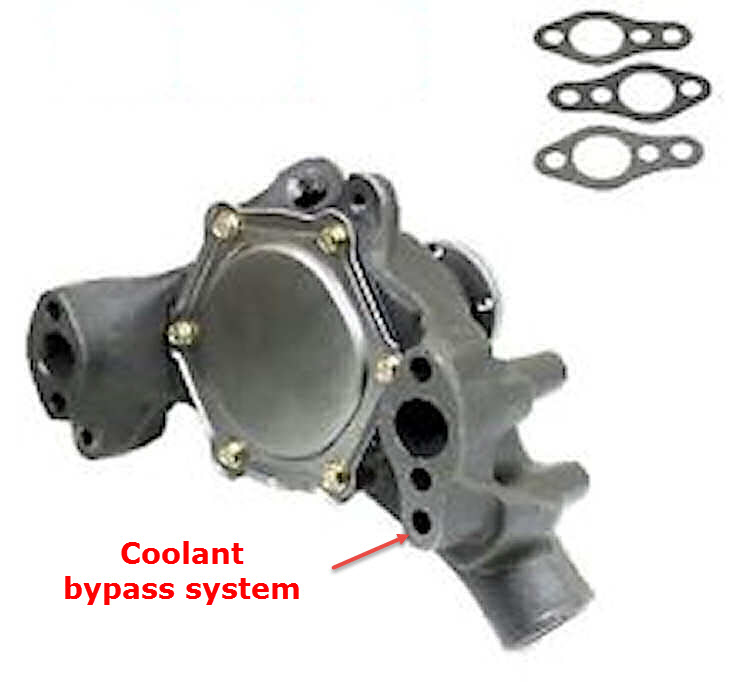
Bypass System
The bypass channel on a small block Chevrolet engine is incorporated into the water pump itself on the driver side and flows into/from the driver side of the engine block. The bypass system is used to circulate water throughout the engine until the thermostat opens.
Ever wonder why when you purchased a replacement water pump for your 283/302/307/327/350 Chevrolet engine the water pump-to-engine block gaskets had 4 holes? The bypass system is incorporated into the engine block and water pump.
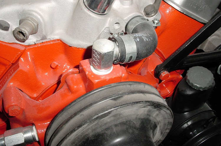
The 327 high performance engine, RPO L79, also incorporated a hose from the top of the water pump to the intake manifold as a second bypass.
Chevrolet’s Mark IV big block 396/402/427/454 engine uses only the hose for its bypass system.
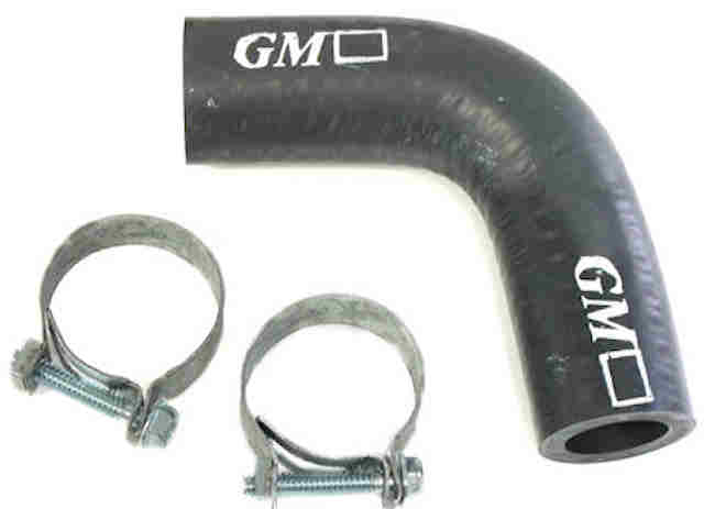
Early 1965 through 1968 Mark IV engine with a “short” water pump uses a bypass hose with a 90-degree bend due to the short distance between the water pump and the intake manifold.
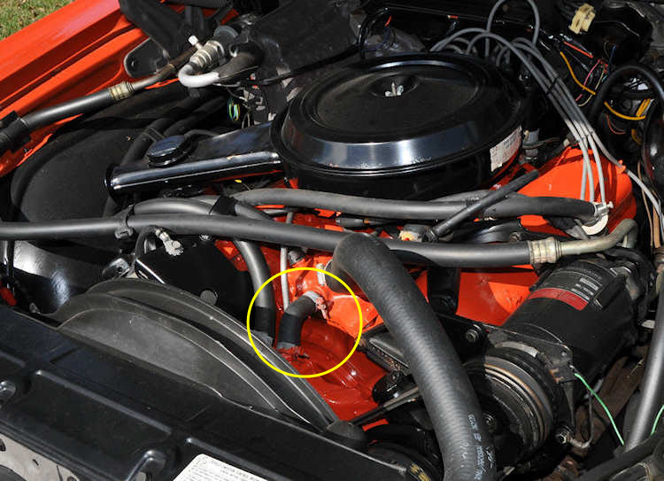
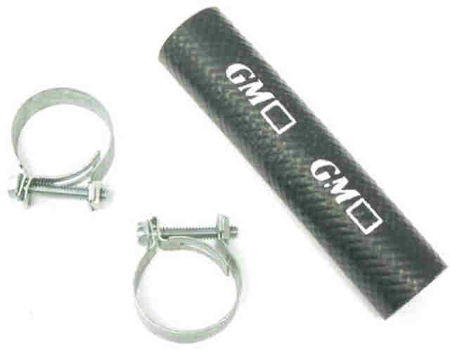
The 1969 and later Mark IV engines have a “long” water pump so the bypass hose is not as ‘bent’ as the early engines. There are molded hoses with GM markings in the aftermarket but many hobbyists will simply use a short length of heater hose to accomplish the same task such as this 1969 L78 engine.
How your car’s instruments work and fixing malfunctions
utomotive gauges are simple and have changed little in the last 100 years. Understanding how they function can make troubleshooting a snap. Some background on the basic principles of gauge operation: Variable resistance to the flow of electricity to a negative ground (body/chassis) affects where the gauge needle moves on the instrument face. Electrical flow can be controlled by switches, resistors, diodes, fuses, and circuit breakers. In the case of analog gauges, the sending unit or “sender” is a variable-resistor contact switch to ground. When resistance to ground is high, the instrument will read low. When resistance is low, the needle will read high. On/off warning lamps are switched by a simple on/off sender.
None of this would be possible were it not for a voltage regulator located on the back of most instrument panels. With the ignition of a nominally 12-volt vehicle on, roughly 12-14 volts of electricity flow to the instrument voltage regulator, which reduces that voltage to approximately 5 volts for the instruments. It’s then a matter of completing the electrical circuit from the gauge to ground. A faulty instrument voltage regulator will either stop current flow to the gauges, or the contact inside will stick, and all instruments (except an ammeter) will give a maximum reading.
Coolant Temperature Gauge and Sender
The coolant temperature gauge operates based on the amount of current flowing to ground via the sender at the engine. Inside the sender is a thermal contactor, which expands or contracts with temperature change. With an increase in coolant temperature, the sender decreases resistance to ground, which increases current flow across the gauge, moving the needle higher. By contrast, cold coolant causes high resistance to ground in the sender, which moves the needle low.
This is a tab-style voltage regulator as used on pre-1969 Ford instrument panels. It converts 12-14 volt current to the 5 volts required. Beginning in 1969, Ford introduced a button-style voltage limiter with printed-circuit clusters.This is a typical pre-1969 Ford coolant temperature gauge, which is identical to the oil-pressure and fuel gauges of the era except for the gauge face.On the reverse are needle-adjustment holes. The screwdriver points to the hole that controls where the needle rests with the ignition off, or zero feedback from the sender. The other adjusts maximum needle travel.Inside, the white arrow points to the resistor, or heating element, that acts on the bimetallic strip (red arrow) that acts on the needle. As current flow through the resistor increases, the strip becomes hotter and moves the needle. When the ignition is turned off, current stops passing through the resistor and the needle returns to rest.Here are two types of coolant temperature senders: A variable resistor type for gauges (right) and a simple on/off type for warning lights.By testing a dry coolant temperature sender with a multimeter (ohmage setting), we
Fuel Gauge and Sending Unit
The fuel sending unit controls the flow of current to ground based on how full the tank is. A float rides on the fuel’s surface and acts on an arm connected to the variable resistor to ground. When the float is high, current flow to ground is low and the gauge reads full. When the tank is empty, there’s high resistance to current flow to ground and the gauge reads low.
Troubleshooting the fuel gauge and sending unit is similar to diagnosing the temperature gauge. Disconnect the fuel-sending unit and ground the plug. If the needle moves to full, the sending unit is faulty and should be replaced. If the gauge does not respond, there is a disconnect in the wiring between the fuel gauge and the sending unit. Alternately, if the float takes on fuel, it will sink, causing an erroneous reading at the gauge, or a corroded or damaged resistor coil may provide a faulty reading.
Oil Pressure Guage and Sender
The oil pressure gauge works much like the fuel and coolant gauges. Inside the oil pressure sender is a spring-loaded piston that – when met with oil pressure – moves a contact back and forth across a variable resistor to ground. With higher oil pressure comes lower resistance and a higher reading, and vice versa for a lower gauge reading. Troubleshooting is identical to the temperature gauge.
Ammeter Versus Voltmeter
An ammeter shows the rate of charge, while a voltmeter registers how much voltage is at the battery. An ammeter reads high when the alternator/generator is charging, and low when the battery is losing voltage due to a draw, such as using a turn signal. Ammeter needles will sometimes dance disconcertingly as a result. A potential problem with ammeters is they are live all the time and – in the case of some vehicles – are not circuit-protected, meaning they are vulnerable to overheating.
The ammeter, once common on Ford and Chrysler vehicles, shows the rate of charge or discharge depending upon which way the needle swings. Unfused ammeters can be a fire hazard because they are live whenever the battery is connected.Direct-connection, shunt-style Ford ammeters can overheat and fail. This unit has a broken wire, yet current continued to flow through to the main wiring loom.
Mechanical Speedometers
Vintage vehicle speedometers are mechanical and thus are not dependent on electricity. They work on the principle of magnetic field in which the faster a magnet spins inside a metal drum within the instrument, the higher the gauge reads. Making the magnet spin is a cable connection between the transmission output shaft, a drive gear and a driven gear, and the gauge.
Mechanical speedometers largely fail due to the absence of lubrication at the speedometer head, which you can fix yourself with a liquid graphite lubricant. The gauge also quits if the cable binds and breaks, but swapping the cable is another relatively easy task. If neither remedy resurrects the gauge, it is best to entrust it to a qualified repair shop, which can also calibrate it.
Speedometer accuracy relies on matching the rear-axle ratio to the drive and driven gears (number of teeth in each). Larger- or smaller-than-stock tire diameters will cause the speedometer to read too fast or slow, a problem that can sometimes be rectified with a new driven gear.
The time-proven mechanical speedometer is simple in function.
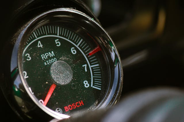
Electronic Tachometers
Most factory tachometers, with few exceptions, are electrically driven by ignition pulses off the distributor or the negative side of the ignition coil. Mechanically driven tachometers work like the mechanical speedometers just mentioned but with the cable typically driven by the generator or crank snout. Electronic tachometers are not user-serviceable and will have to be sent to an instrument repair shop for restoration.
Electric-based tachometers operate on ignition pulses from the ignition system.The faster the pulses, the higher the tachometer will read. Tachometers should be serviced by a qualified instrument repair shop.
Not all cooling system issues are caused by faulty parts, especially after a new installation or fluid change. The biggest mistake most DIYers make when adding coolant to the radiator is not properly burping the system. There are multiple ways to do this, depending on the type of system (open vs. closed), position of the radiator in relation to the engine, and the engine itself.
Feeling Bloated?
The issue with filling a radiator is that air is easily trapped inside the engine, hose, and heater core, leaving you with multiple issues. The first one is that your cooling system is not properly filled. An air pocket not only takes up room where coolant needs to be, but also can block coolant from entering other areas, so you think the system is full, but isn’t. If you only poured a half of a gallon, but the tank is full, you likely have an air lock.
Symptoms of an air pocket in the cooling system include erratic temperature swings, overheating, no heat from the HVAC (when set to heat), or low temperature readings. Notice that we mentioned temperature twice. This is because there are two different symptoms here. An air pocket can cause erratic temperature readings, such as going from cold to normal operating temp in seconds, and then getting very hot, and then suddenly swinging down to the normal operating range again. This can be caused by an air pocket interrupting the flow of water through the thermostat. The other issue, which is more serious, is air becoming trapped around the temperature sensor, so the gauge is not seeing the coolant at all, so it can’t read the actual temperature.
While any engine can get air pockets, some engines are inherently prone to trapping air. LS engines for instance have a habit of getting air locks. The steam lines in the heads help reduce this, but it takes time for them to work out naturally. If the engine or heater core are mounted above the radiator cap, air is easily trapped in the system.
Under Pressure
While the average DIYer doesn’t have to fill their cooling system often, the reality is that for less than $100, you can own a cooling system filling kit that uses vacuum (negative pressure) to draw all of the air out of the entire cooling system, and then with the flip of a valve, that same vacuum draws fresh coolant into the system. This is the fastest way to guarantee that the system is not only full, but the vacuum process also shows you if there are any leaks. A slightly loose hose clamp will ruin your day if the hose pops off on the highway, finding it before that happens is worth the cost of the kit alone. Some filling kits also have pressure pumps, which are very useful for finding leaks in a system.
The basic process with a vacuum filler is as follows- attach the cap valve to the radiator, close any expansion tank cap. Connect an air compressor to the venturi valve, open the valve to draw vacuum on the cooling system. The radiator hoses may collapse, this is normal. Once the gauge reaches about 25 inches of vacuum, close the valve and disconnect the air compressor. The vacuum should not drop, it should hold at the same level for at least 30 seconds. You don’t need to let the system rest under vacuum for a long period of time. If there is a leak, the vacuum will not hold for long.
Insert the filler tube, which is attached to the main valve, into a fresh jug of coolant and open the filler valve. This will draw coolant into the engine. Once the vacuum pressure is gone, the process is repeated until the system is full. This usually takes 2-3 vacuum draws for most vehicles.
Manual Fill
Most DIYers manually fill their cooling systems, which is just fine, it just takes a little more time and effort. Start with a cool engine, (Never open a radiator on a hot engine) fill the radiator with the correct type of coolant until it is at the top of the radiator. Wait a few minutes for it to lower, as the air takes some time to work its way out. Once the radiator (or expansion tank) is full and no longer dropping, start the engine and allow it to come to operating temperature. Turn the heater to max heat, this opens the heater core coolant valve, allowing coolant to flow through the heater core as well, where air can become trapped. During the warmup period, the coolant level will drop. Add more coolant as it drops below the bottom of the water neck or “full” mark on the expansion tank. Leave about a half inch of air below the radiator cap mount, this provides room for the coolant to expand when hot.
Once the engine is at operating temperature and the tank is full, replace the cap and go for a drive. Bumpy roads are great for breaking up trapped air. Return home, allow the engine to cool, and then open the cap, top off as necessary. It may take a couple of days to get all the air worked out of the system.
Got A Headache?
An old timer once taught us a trick years ago for dealing with stubborn air pockets. His trick was to remove the thermostat, pry it open with a screwdriver, and slip a couple of headache pills between the body and spring of the thermostat, and then reinstall the T-stat. The pills held the thermostat open for about 15-20 minutes once the engine was started, allowing the coolant to flow freely, purging any trapped air in the engine within minutes. Within 30 minutes, the pills completely melt, and the thermostat operates normally.
If you find yourself fighting a tricky air pocket, you could have a small air leak that is big enough for air to pull in, but not quite large enough for coolant to weep through. The vacuum kits are really good at finding these leaks. If you pull vacuum on the system with coolant in it, you can often hear the bubbles in the tank.
Ensuring that your vehicle’s cooling system is properly filled is paramount to its operation. Leaks and air pockets generate a lot of frustration. Take your time to do the job right and your engine will run at the correct temp without issue season after season. For more information on setting up your vehicle’s cooing system needs, give the folks at U.S. Radiator a call at 800-421-5975.
The Corvette rear script or emblem, along with virtually all other decorative trim and insignias on Mid-Year Corvettes, is made of chrome-plated pot metal. Over time, due to exposure to moisture and the elements, the chrome plating develops pits and pocks as the pot metal underneath the plating reacts to changes in moisture content and air-borne chemicals. While replacing this script is a bit more involved then one would think at first blush, it’s easy enough to do with some simple tools and a couple of hours worth of labor. Here’s how to go about it with a new script from Zip Corvette Parts, 8067 Fast Lane, Mechanicsville, VA 23111, 1-800-692-9632.
Step 1
01: Close examination of this original 1967 Corvette rear script reveals pitting and general weather wear. Additionally, this emblem caused an annoying rattle at idle speed due to vibration, since it wasn’t properly mounted; apparently, a previous owner of this car had removed it and didn’t replace it correctly.
Step 2
02: It’s necessary to remove the rear valance panel so you’ll be able to reach upward for access to the script mounting nuts. The first step in removing the valance panel is to remove the nut, bolt and washers on the inside of each quarter panel that secure the lower end of the valance panel. Our project car has side exhausts; however, if your car has rear-exiting exhausts, it will be necessary to disconnect the muffler hangers from the mufflers so they can drop down for panel removal later.
Step 3
03: A total of eight 7/16” bolts secure the valance panel at the rear of the car; 3 are located beneath each bumper, and these are removed next.
Step 4
04: The rear license plate must be removed next for access to the two remaining 7/16” bolts located behind it.
Step 5
05: The lower license plate bezel mounting bracket screws are removed next. When these are out, the valance panel can be removed by pulling down gently on it.
Step 6
06: Here’s the rear of the car with the license plate and the valance panel removed. The stainless steel tray at the bottom is a magnetic unit that’s very handy for holding screws, bolts, washers and nuts that will be used again for reassembly. At this point, you can reach your arm up into the rear deck area next to the gas tank and use a 5/16” wrench to loosen the speed nuts holding the rear script on the car.
Step 7
07: The old Corvette or emblem script is at the bottom with the new one at the top. The wear on the old one is evident when you compare it with the new genuine GM Restoration Part replacement unit.
Step 8
08: The source of the vibration and rattle the old script (top) made is now evident when seen from the back; only two mounting spikes remained on the old one (at the bottom and top of the second “t” in Corvette), instead of all five required for a solid mount as shown on the new emblem (bottom).
Step 9
09: Here’s the rear deck after removing the script, showing evidence that it was held on with butyl tape and glue. Shoddy workmanship by whoever did this, indeed!
Step 10
10: It took quite a bit of scrubbing with a shop towel moistened with denatured alcohol and some gentle scraping with a single-edged razor blade to remove the gummy residue of the butyl tape and the dried glue, but it was necessary to clean the surface for proper mounting of the new script.
tep 11
11: Along with the rear script, a speed nut kit was also ordered from Zip Products. Five of the smallest speed nuts are required for mounting the script, and they’re shown here positioned on the mounting spikes.
Step 12
12: Use a 5/16” socket to thread the speed nuts all the way down on the spikes; this is necessary, since the speed nuts actually cut their own threads into the spike. Run each nut down and back up again about three times for each spike so the threads cut in nicely. This makes threading the speed nuts on considerably easier when you’re securing the script.
Step 13
13: Position the script spikes over the holes in the deck and press down on the script evenly. Then reach your arm up inside the rear deck and thread each of the speed nuts on their respective spikes. When all 5 nuts are well started, use your other hand (or an assistant) to push down on the script while you tighten the nuts. You’ll find that a 5/16” gear wrench is the best tool to use for working in this very cramped area, since there really isn’t enough room to use a ratchet and socket. Here’s the new script installed and secured – quite a difference between how it looks now and how it looked when we started!
Steve, owner of C&S Corvettes and the CorvettePartsCenter.com website steps in for Lyle while he’s on holiday. Steve talks about an issue we hear over and over…getting locked out of a C3. Steve demonstrates how to get back in, unlock the car and resolve the issue without destroying your car’s door panel. www.CorvettePartsCenter.com
Step by step assembly of a C3 Corvette door. From a bare shell to a completed door.
How to REPLACE C3 Corvette DOOR HANDLES
This is the most comprehensive, step-by-step how-to video on how to remove, then install, a C3 Corvette exterior door handle. Removing or installing a C3 Corvette outside door handle is challenging but achievable by the average DIY mechanic with the right tools. The door panel has to come off and a couple of items must be loosened and moved out of the way to get the job done. Also, if yours is broken or simply old and rusty and in need of replacement, you will need to have a suitable part available. A basic understanding of how clips connect to rods, for example, and how to route the latch release rod are important details covered in great detail so you can get the job done quickly and correctly.
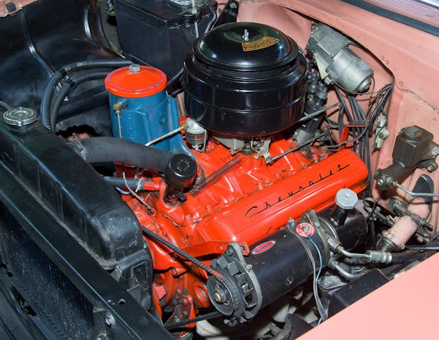
The engine in my ’55 Chevy requires tuneups at 10,000 mile intervals. Fortunately, that’s about every ten years for this occasionally driven car. But access to the distributor, which is all the way at the rear behind the coil and air cleaner and under the wiper motor, is difficult. Note also the generator/power steering pump unit that restricts access to left bank spark plugs. Paul Stenquist
Today’s automobiles don’t require regular tune-ups like the cars of yore once needed. The electronic sensors and computers that regulate spark, timing, and fuel mixture are not maintenance items, although they do have to be replaced if they fail. And in today’s engines, spark plugs operate well for 100,000 miles or more. There are still filters to be replaced and components to be checked, but modern maintenance procedures are far different than what we old-timers remember.
Older cars need more attention on a more frequent basis. A typical owner’s manual for a 1950s car calls for a 10,000-mile that includes swapping out spark plugs, replacing points and condenser, and checking the carburetor idle mixture and ignition timing. In addition, recommended maintenance calls for oil changes every 2000 miles and regular lubrication of numerous components in the engine and chassis. With an older classic or an ancient beater, regular maintenance of ignition parts and filters is critical to smooth running and adequate power. Let’s walk through the process together.
Step 1: Swap out the spark plugs
To replace the spark plugs, carefully remove the plug wires and their insulating boots from each plug. If you think you’re not going to be able to tell which wire belongs to which plug, tag the wires. Inspect them: If you see deterioration of the insulating boots, or severe burns or cracking of the cables, replace them. Likewise, if the cables’ contacts are corroded to the point where they can’t be cleaned, replace the wires.
To remove the spark plugs, you’ll need a 3/8-inch drive ratchet and a spark plug socket. In most cases, a short extension allows better access. A ratchet with a flex head that can rotate to different angles can be helpful. A 5/8-inch or 16-mm hex socket will fit many plugs. Some Fords use plugs with a 9/16th-inch hex. A few European and Asian vehicles use 14mm plugs, and there are a few applications that use plugs with a 7/8-inch, 3/4-inch, or 18-mm hex. Most older American cars are fitted with plugs that have a 13/16-inch hex.
Some BMWs are equipped with plugs that require a thin-wall, 12-point, 14-mm socket for removal. Check the specs for your car before purchasing a tool.
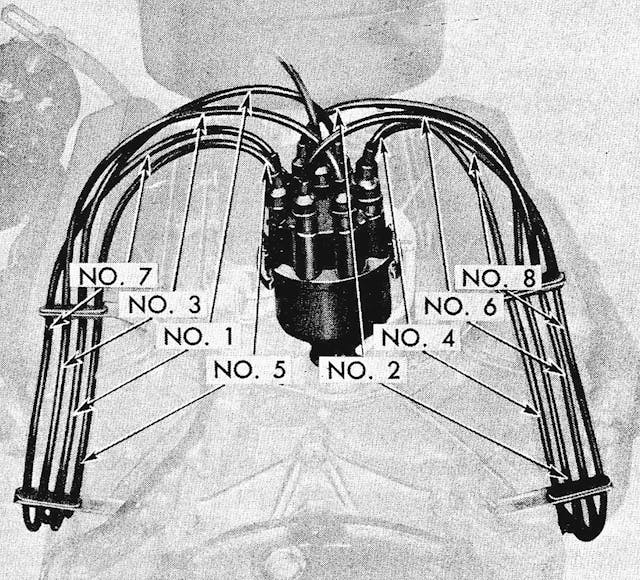
Spark plug wires are plugged into the distributor cap according to the firing order of the engine and the direction of the distributor’s rotation. This ’55 Chevy small-block has a firing order of 1-8-4-3-6-5-7-2 and it rotates in a clockwise direction. Note how the wires disappear in looms behind the engine: That arrangement means it’s best to indicate the cylinder number of each wire with a tag before disconnecting them. You can determine the order based on their position in the looms, but that assumes that they are positioned correctly. GM
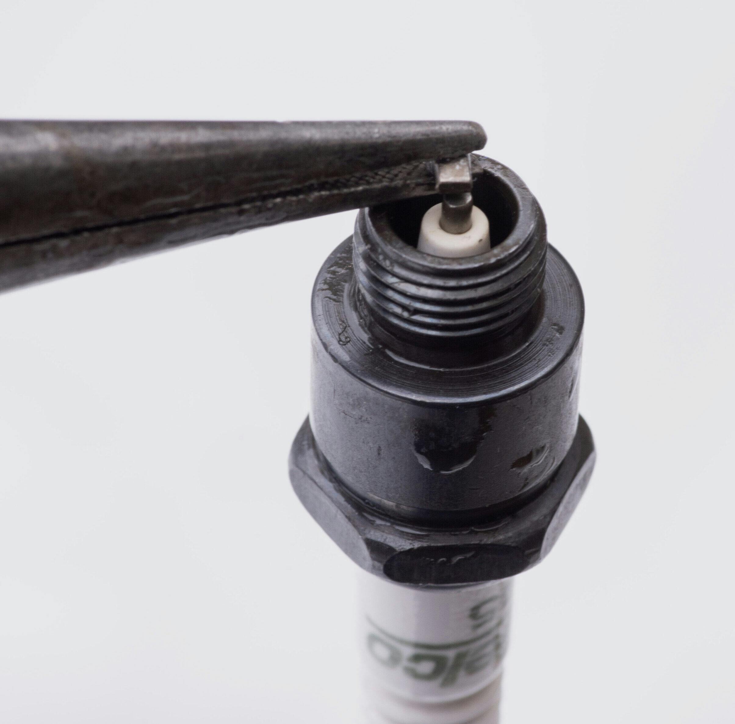
Once the spark plug is fully loosened, extract the magnet or a rubber sleeve inside that grips the plug (most cars have one or the other). On many cars, that combination of ratchet, socket, and short extension is all you’ll need, but on some models, it may not allow you to access all the plugs. My ’55 Chevy V-8 is equipped with a combination generator/power steering pump, and some left-bank plugs are best serviced from under the car with a 13/16-inch open-end wrench.
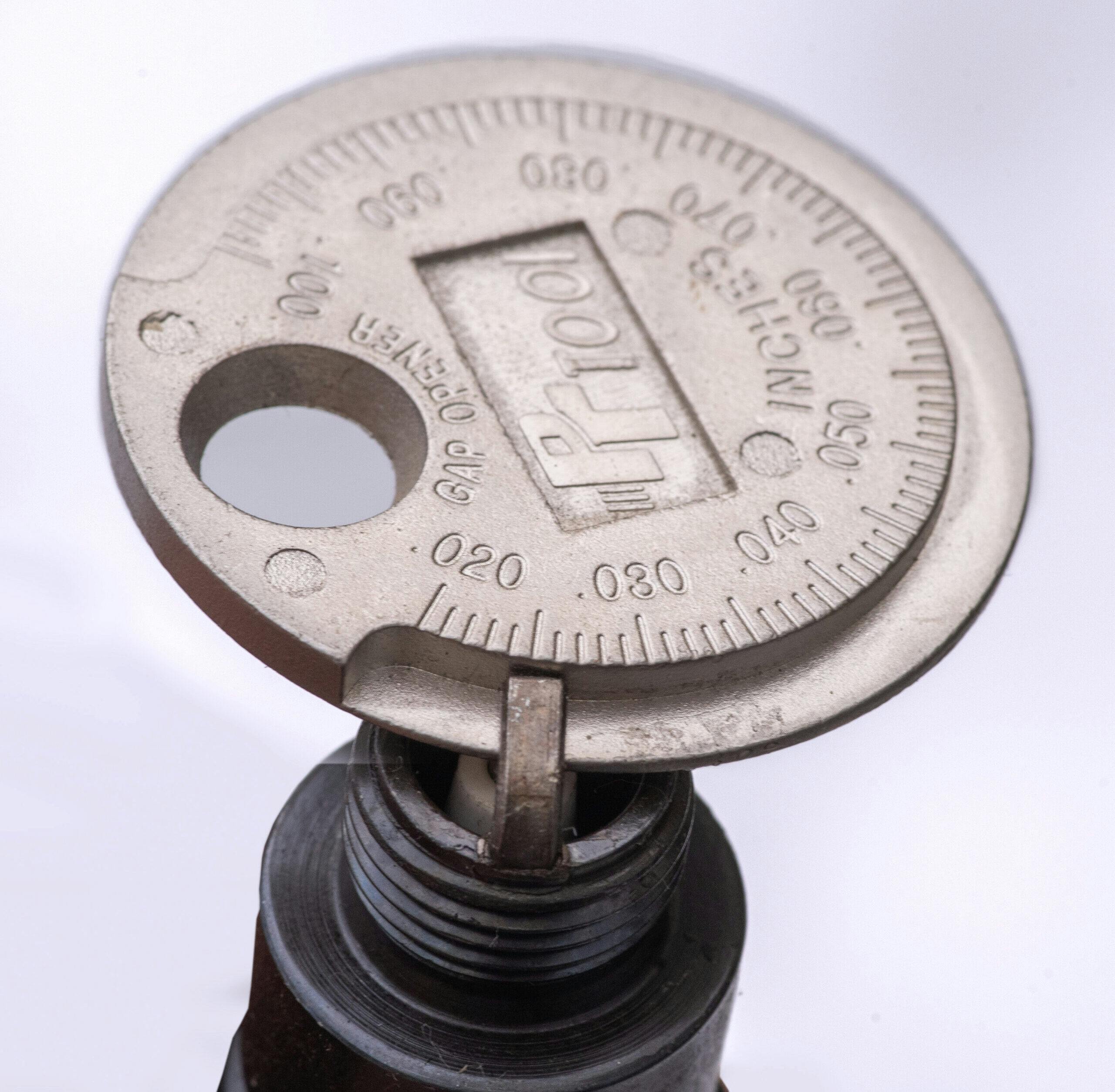
Before installing the new plugs, inspect them for damaged insulators or bent electrodes, then set the gap between the inner and outer electrodes. For most older vehicles with coil ignition, a gap of 0.025 inches is generally recommended. For even older vehicles with magneto ignition, the gap should be set to 0.020 inches. You can use a conventional feeler gauge to set the gap, but a round wire gauge is better. I have a tool that consists of a calibrated ramp of gradually increasing thickness. By sliding the plug along the ramp, the gap is easily measured. Your auto parts counterman may stock gapping tools as giveaway items. At the very least, they are inexpensive.
This spark-plug gap measuring tool incorporates a ramp of varying thickness around its circumference. You can measure the gap by sliding the plug along the ramp until it stops. Paul StenquistDon’t adjust the gap by banging the plug against a hard surface. Use needle-nose pliers and bend the electrode carefully. A damaged plug can short and cause a misfire. Paul Stenquist
If you have to change the gap, carefully bend the outer electrode with needle-nose pliers or with the slot on the gapping tool. Don’t bang the electrode against a hard surface: You might crack the insulator, which can cause a short.
Some plugs come with the metal gasket installed. On others, you have to work it on over the threaded end. Place a small amount of dielectric grease on the plug threads and install them. Tighten moderately. If space permits the use of a torque wrench, torque them to 25 pounds. If you can’t use a torque wrench, screw the plugs in by hand until they seat, then tighten another half-turn with your wrench. It’s always best to start them by hand; there’s nothing like a cross-threaded spark plug to ruin your day.
Step 2: Service the distributor
The replacement and adjustment of distributor parts is fairly easy on many cars, as the distributor is mounted at either the side or at the front of the engine. Except on my ’55 Bel Air, in which the distributor at the rear of the engine and snug up against the firewall. One must either have really long arms or lie atop the engine to reach it.
On some cars, the distributor cap can be removed with the spark plug wires attached. On my old Chevy that’s near impossible, as the wires are routed behind the engine, and there’s not much room for maneuvering. In any case, you’ll want to remove the wires from the cap at some point to check for corrosion or other damage. I mark the position of the number one cylinder’s wire in the cap, then pull all the wires out of the cap, wiggling each a bit as I tug on them so as not to damage the wire terminals. Armed with the firing order (1-8-4-3-6-5-7-2 for my Chevy) and the rotation (clockwise), it is easy to reinstall them correctly. But because the wires disappear behind the engine and under the exhaust manifolds before they arrive at the spark plugs, I number them as well, wrapping a short piece of masking tape with the cylinder number written on it around each wire.
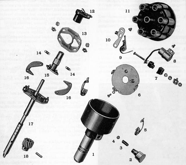
An exploded view of the ’55 Chevy distributor. If the shaft bearings, which are located within the case, are worn out, the breaker point air gap won’t remain constant and the ignition dwell will fluctuate. GM
After removing the distributor cap, have a look inside. There you’ll see contacts that distribute voltage to the spark plugs for each of the cylinders. For example, the cap for an eight-cylinder engine has eight contacts evenly spaced within the circumference of the cap. If the contacts are badly corroded or if the cap is damaged, they should be replaced. The contacts will likely be mildly corroded. In that case, clean them with a small, sharp knife or similar tool.
Remove the rotor from the top of the distributor shaft. Check for corrosion on the conductor at the rotor’s outer edge. Mild corrosion can be removed with an emory cloth or small file. Severe corrosion that has caused pitting or loss of material is grounds for replacement.
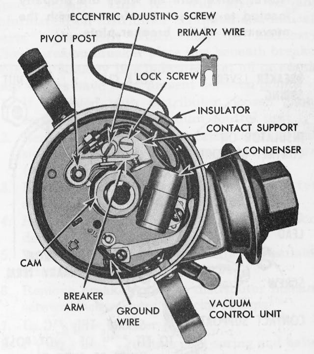
This ’55 Chevy distributor is a simple affair and typical of many older cars with a single set of breaker points and a condenser. A terminal on the points is connected to the negative side of the coil via the primary wire. The condenser is connected to the other side of the terminal. The points and condenser can be removed together after the primary wire is disconnected. GM
Within the distributor, you’ll find the breaker points and condenser attached to the breaker plate with screws. While old-time service manuals suggest that points can be cleaned and readjusted if they are in fairly good condition, I replace them if I’ve already dug in this deep. Many distributor parts for older cars are still available from standard aftermarket sources, even for cars that are 70 or more years old. And they’re generally not very expensive: Breaker points for my ’55 Chevy, as listed in the East Coast Chevy parts catalog, sell for $15.00. Other distributor parts are equally inexpensive.
Ignition parts for less common cars may be harder to find. But suppliers who specialize in servicing classics and exotics should have them. Of course, you may pay considerably more. Ignition points for a Ferrari 250 GTO are $53.50 from awitalian.com.
The breaker points are attached to the distributor breaker plate with one or two screws. You might also find an eccentric adjusting screw that can close or open the point gap when it’s turned with the locking screw loosened. Be careful removing the screws, as they’re small and it’s easy to drop them.
On most systems, the condenser is wired to the breaker points via a screw terminal and is held in a bracket that is attached to the breaker plate with one screw. The points and condenser can usually be removed together.
The breaker point air gap is measured with the points’ cam follower on the peak of the distributor cam. Moving the assembly away from the cam reduces the gap; moving it closer increases the gap. Dwell angle indicates the number of degrees of rotation that the points are closed and charging the coil. Increasing the breaker point gap reduces the dwell angle. Reducing the gap increases dwell. Image by Eric Garbe, courtesy of Counterman/Babcox Media
Before installing new points and condenser, apply a very small amount of dielectric grease to the distributor shaft cam. Install the points and condenser. Some points are adjusted with a slotted screw hole in the breaker point assembly that enables adjustment of the installation position. The points on most 1957 to 1974 GM cars are adjusted using an 1/8-inch Allen socket adjustment screw that can be accessed with the distributor cap removed, or through a sliding metal window in the cap. Thus, on these models, final adjustment of the points can be completed with a dwell meter after reassembly. But whichever type of breaker point adjustment you’re dealing with, it’s important to set the air gap before buttoning things up, even if you intend to fine-tune the adjustment with a dwell meter after starting the car.
The breaker points are fitted with a cam follower that rides on the distributor cam. To adjust the air gap, crank the engine until the cam follower is on a peak of the cam. Then adjust the gap to 0.015 inches by moving the breaker point assembly in or out before tightening the screw or screws that lock it in place. On those GM cars with the Allen adjustment, just turn the Allen screw until the correct air gap is achieved.
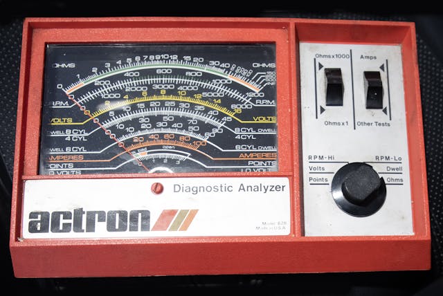
Install the rotor, cap, and plug wires. Then, if you have a dwell meter, attach its black lead to ground and its green lead to the negative terminal on the coil or as directed by the instructions for your meter. Dwell is the number of degrees of rotation that the points remain closed. Start the engine. You should see a reading of about 30 degrees dwell for V-8 engines. A degree or two in either direction is okay. A six- or four-cylinder engine will be happiest with a couple of degrees more dwell.
A dwell meter measures the angle of dwell with the engine running. This Actron meter is over 40 years old and still working well. The meter’s black lead is attached to ground, and its green lead is attached to the negative terminal of the coil. Note it can also serve as a tachometer, voltmeter, ohmmeter, ammeter, and points resistance gauge. Paul Stenquist
If dwell is not correct, you will have to readjust the points. If you are working on a ’57 to ’74 GM car, you can adjust the dwell while the engine is running by turning the 1/8-inch Allen screw, accessed through the metal shutter in the distributor cap. For most other cars, remove the distributor cap and readjust the air gap, moving the breaker point assembly closer to the cam for less dwell and further away from the cam for more dwell. If dwell bounces around more than a degree or two, the distributor shaft bearings are probably worn, and the distributor should be replaced.
Step 3: Check ignition timing
After installing new points, a check of ignition timing is necessary. Attach your timing light inductive lead to the number one spark-plug wire, and attach its black and red power leads to positive and negative contacts. Disconnect the vacuum advance and plug the vacuum line. On most cars, there will be a line on the harmonic balancer that indicates top dead center (TDC) for the number one cylinder. Behind the harmonic balancer, on the engine, there will be a degree scale. With timing light attached and engine running, aim that line at the degree scale. The flashing light will indicate how many degrees before top dead center the plug is firing. The spec for my Chevy is 8 degrees before top dead center (BTDC), which is indicated by four lines on the scale. With today’s higher octane fuels, I set it to 10 degrees BTDC.
After replacing and adjusting the breaker point, check the timing with a timing light. The light freezes the TDC mark on the harmonic balancer, indicating when the number one cylinder is firing. On the pictured ’55 Chevy engine, each line on the scale is two degrees. In the photo, the number one plug is firing at 4 degrees BTDC. The specification is 8 degrees. GM
Step 4: Replace filters
At minimum, your car probably has filters for air, oil, and fuel. Of course you should change your oil filter every time you change your oil. And for a classic car that is driven infrequently, oil change intervals should be 2000 miles or every two years.
Fuel filter intervals vary widely by filter type, and many classic owners who don’t put many miles on their car may never have to change it. But a good rule of thumb calls for replacing the fuel filter after 20,000 miles of driving.
Air filters made of paper or synthetic material should last at least 20,000 miles. Oil bath filters, like that on my ’55 Chevy, should be cleaned and refilled with oil at tune-up time. But the filter housing oil level should be checked every 1000 miles or so. I clean the wire mesh element of the oil bath in a solvent bucket and then blow it out gently with the air gun. I then douse the element with SAE 50 engine oil and fill the reservoir to the full indicator mark with the same oil. If temperatures are expected to remain below freezing for an extended time, I use SAE 20 oil. When servicing the oil bath air cleaner, I cover the areas of the engine around the carburetor with plastic drop cloths, because drips are inevitable.
Step 5: Adjust idle mixture
Before 1980 or so, carburetor idle mixture adjustment was an important part of a tuneup. Begin by setting the idle rpm using the adjustment screw on the carburetor throttle linkage. For my old ’55, GM recommends setting the rpm to 450 rpm. If you have a dwell meter, it probably doubles as a tachometer. A vacuum gauge will also be necessary to pinpoint the idle mixture setting.
Unsplash/Hasnain Sikora
With the vacuum gauge attached to a manifold vacuum port, turn the idle mix screw gradually in clockwise and/or counterclockwise direction until you find the spot where rpm peaks and the vacuum reading is highest. If that increases the idle rpm above the spec for your car (or what you’re comfortable with in terms of vehicle creep and smooth idle), reset the idle speed via the idle speed screw on the throttle linkage, and then recheck the mixture adjustment. If you’re unable to detect any difference in engine performance as a result of this procedure, you may have a vacuum leak or a bad carburetor.
If you don’t have a tachometer or vacuum gauge, you can probably get a good approximate idle mixture setting just by adjusting for what your ears tell you is the maximum engine speed. A lot of old timers set idle mix strictly by ear, made possible through lots of experience.
In every case, lots of experience is a mechanic’s best friend.
Big Changes at Cap-A-Radiator Beginning July 5 th, 2023
Cap-A-Radiator will be merging with Acme Radiator in Islip Terrace. Cap-A-Radiator’s expertise in antique and classic car radiators will now be combined with Acme’s heavy duty radiator services to offer unbeatable knowledge and coverage in the field of cooling systems, fuel tanks, heater cores and air conditioning. Cap-A-Radiator’s phone number of 516-293-9026 – for the last 41 years – will stay the same but will now ring in Islip Terrace. Bill Carberry will still be at the other end of the phone and will continue to help you with all your cooling system needs, especially on older vehicles. Cap-A-Radiator, 49 Carleton Ave, Islip Terrace NY 11752 516-293-9026 or 631-581-9199 caparad@hotmail.com or bobby@acmeradiator.net
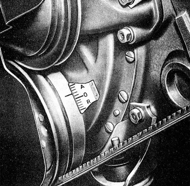
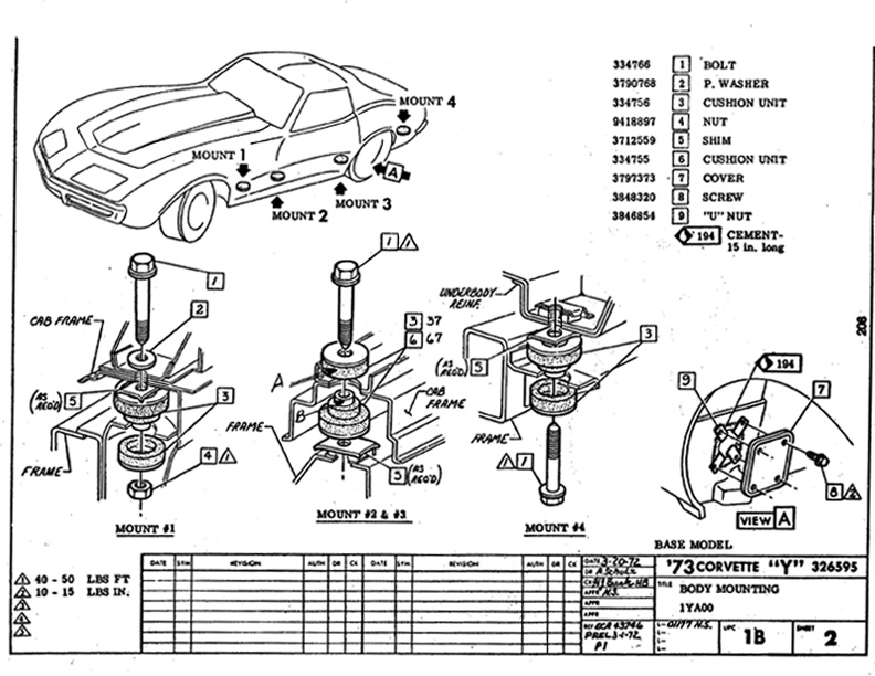
There are only 8 body mounts on 1963-1982 Corvettes so replacing them doesn’t sound daunting. If a Corvette has led a truly dry, garaged life, body mount replacement is straightforward. However, most Corvettes 40 plus years old have accumulated a bit of corrosion on their steel components. Particularly affected are the parts and fasteners that often suffer rain and road splash.
That’s where this series of three tech articles comes in. Rusted fasteners can cause problems with this project. The assembly manuals and the service manuals can’t help here. This, the first article, will start with the body mount that is least likely to present a problem, the front, which is labeled #1. Then we will focus on removing the body mount that is most likely to present a problem, the rear mount, labeled #4.
The work shown here is on a 1973 Corvette, the first year that had rubber body mounts. The same rubber mounts were used until the end of the C3 run in 1982. The previous years, 1963-1972 used metal body mounts but the procedure is similar. Zip Corvette offers both of these types of body mounts in complete kits and also offers polyurethane replacements.
02: The front (#1) mount bolts are the easiest to remove. Access to the right side mount is fairly open. Reach up to place a 5/8-inch box wrench securely on the bolt head.
Step 3
03: Use an 11/16 deep socket on the nut. A ½-inch breaker bar or torque wrench may be needed to break the nut loose. After that, an impact wrench helps spin the nut off. Tap the bolt up and out. Note the #1 body mount bolt uses a thick washer.
Step 4
04: On the left side, reach up over the frame or down from the engine compartment to place the 5/8 inch box wrench on the bolt head. On this car, removal of the splash pan was not needed.
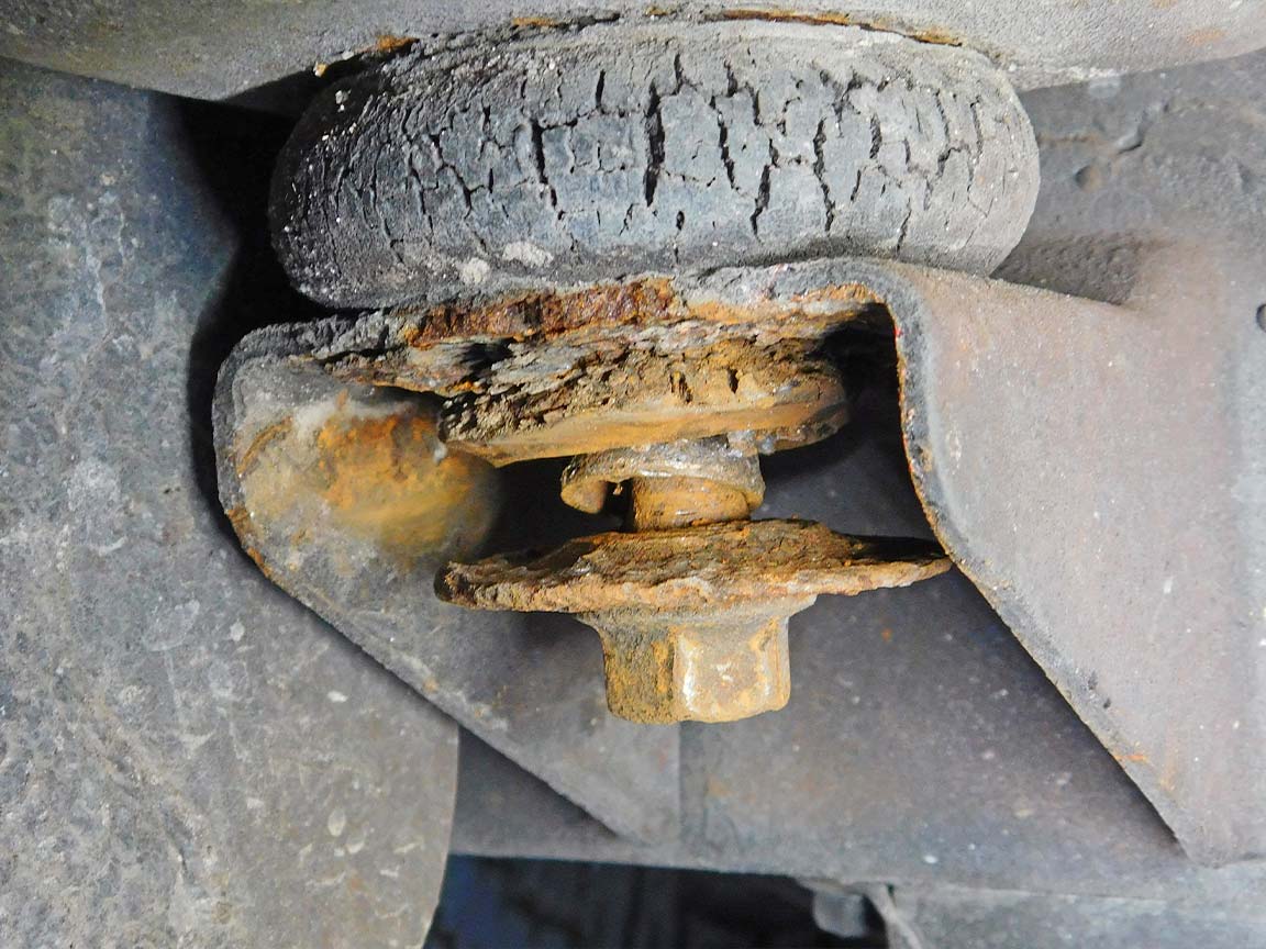
Step 5
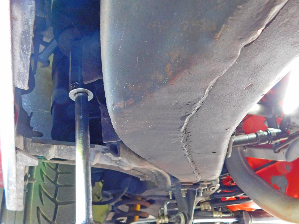
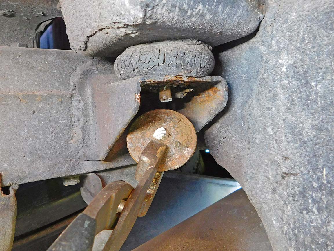
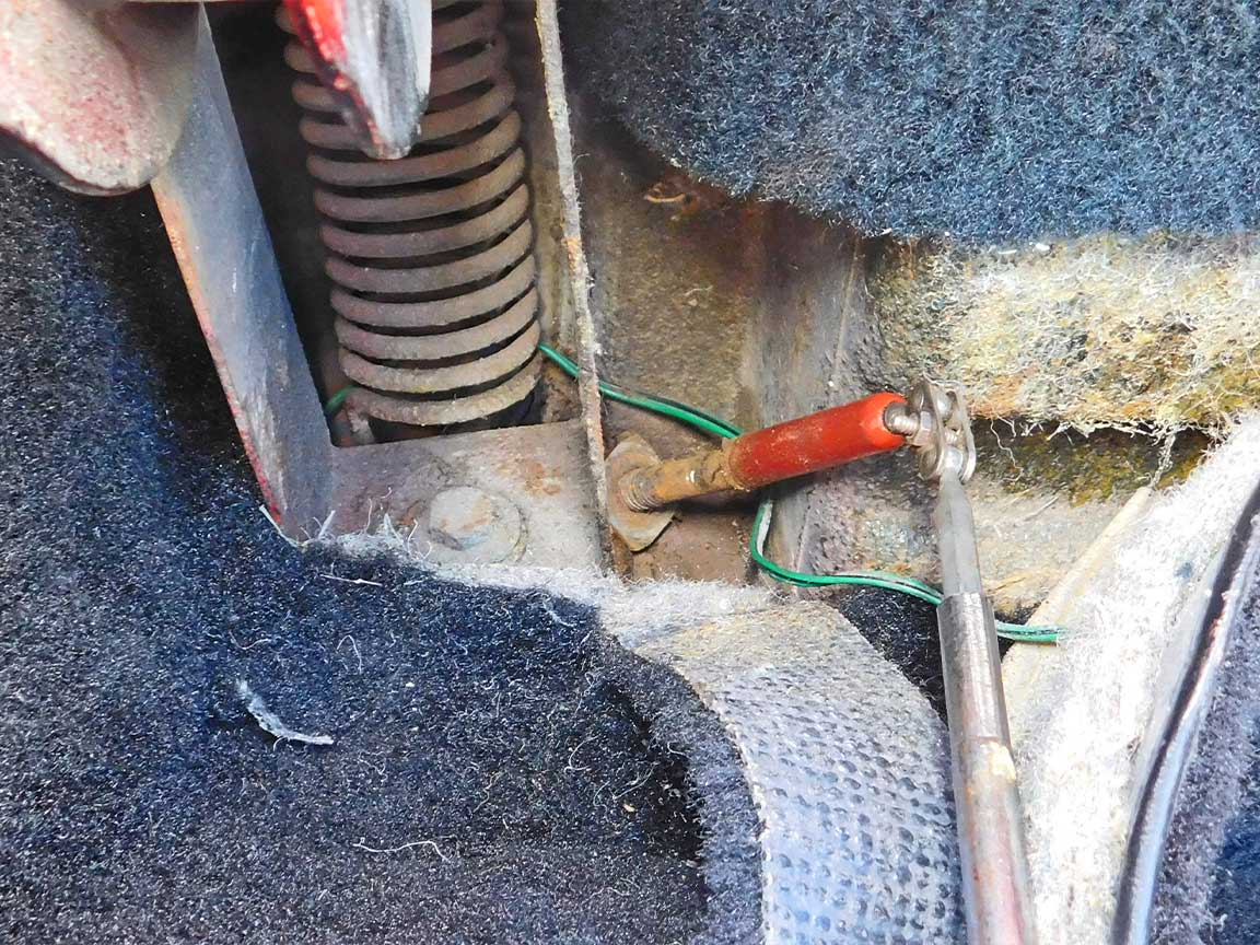
05: The rear (#4) body mounts are often an entirely different situation. The bolt goes up into a small cavity which has a nut in a thin cage. Over years, water gets down into the cavity that surrounds the nut and its thin cage. When this happens, rust can eat away at the nut, bolt and cage. Zip Corvette offers replacements for all these parts.
Step 6
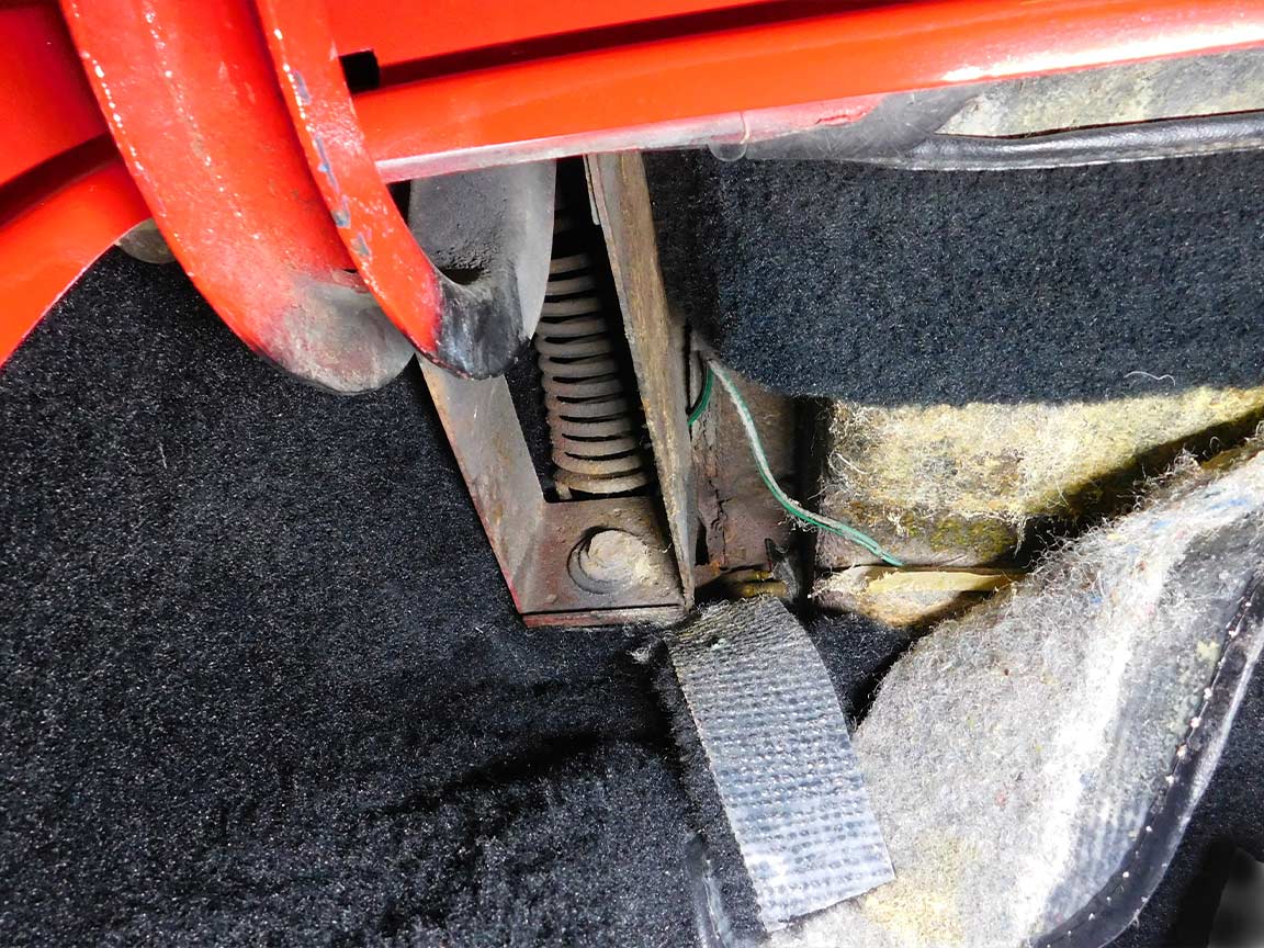
06: The cage and nut are not visible. Pull the carpets back a little if necessary to access the cavity located in the rear compartment corners. Tip: Insert a magnet down into the cavity to determine if substantial rusting has occurred. If little or no rust is picked up, spray penetrant down there to increase the chance of unscrewing the bolt.
Step 7
07: If a lot of rust particles and small metal pieces cling to the magnet, there is no sense in applying penetrant — unscrewing badly rusted bolts would be a lost cause. Plus it’s good to avoid the lingering smell of penetrant in the passenger compartment.
Step 8
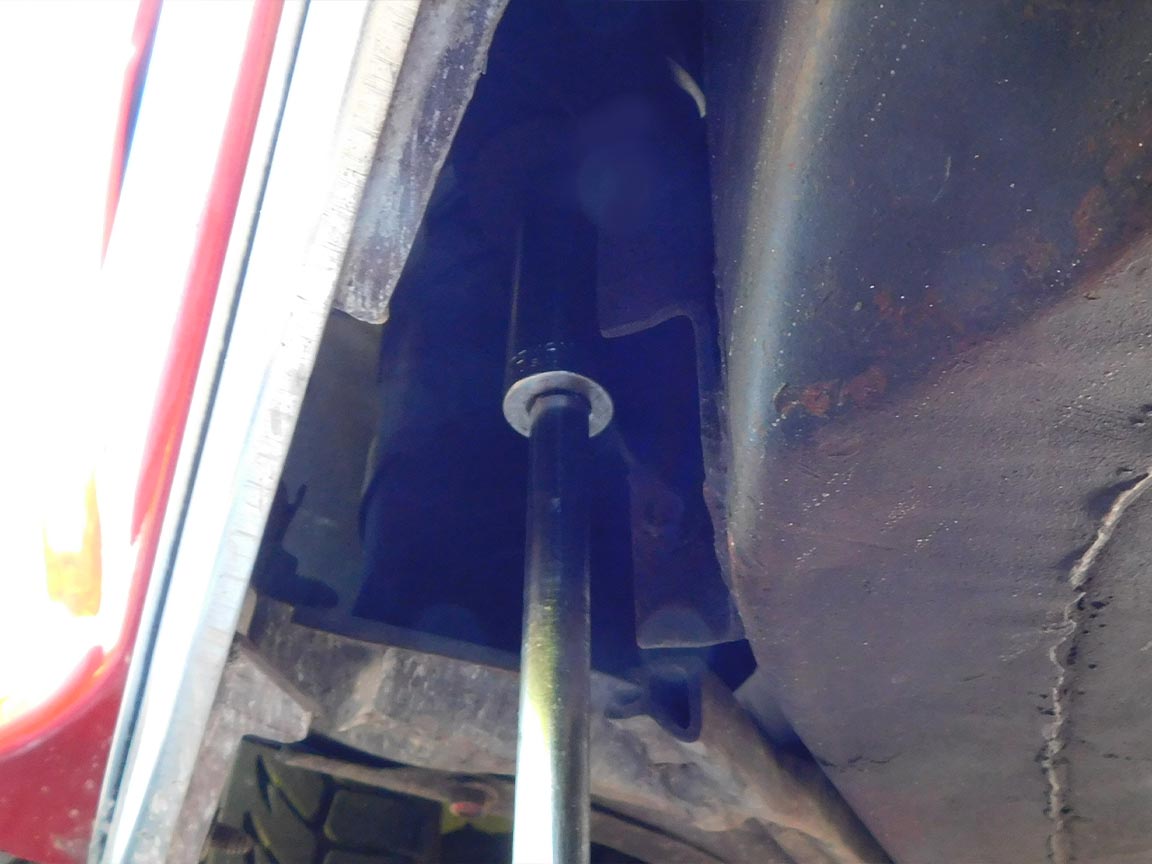
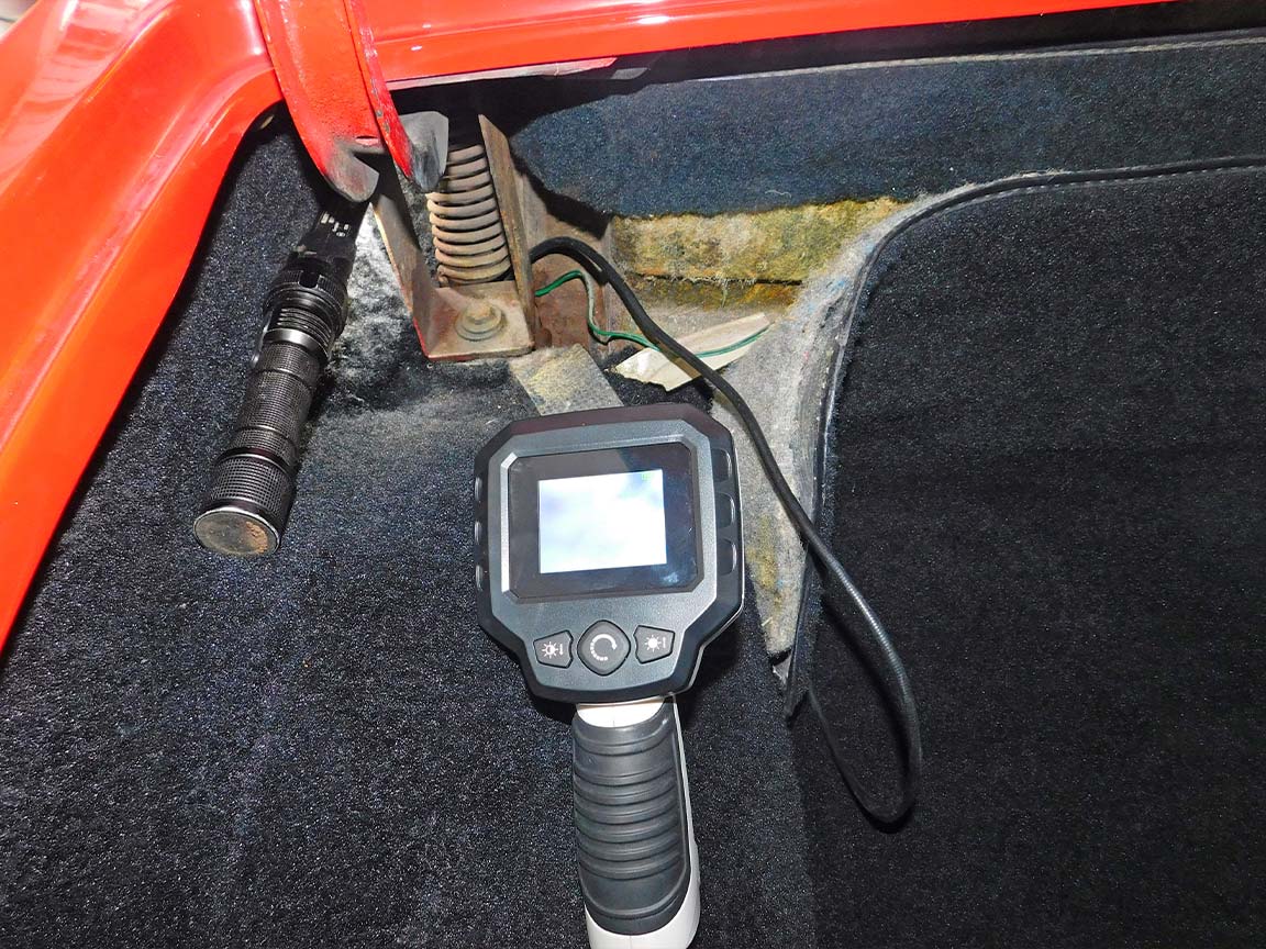
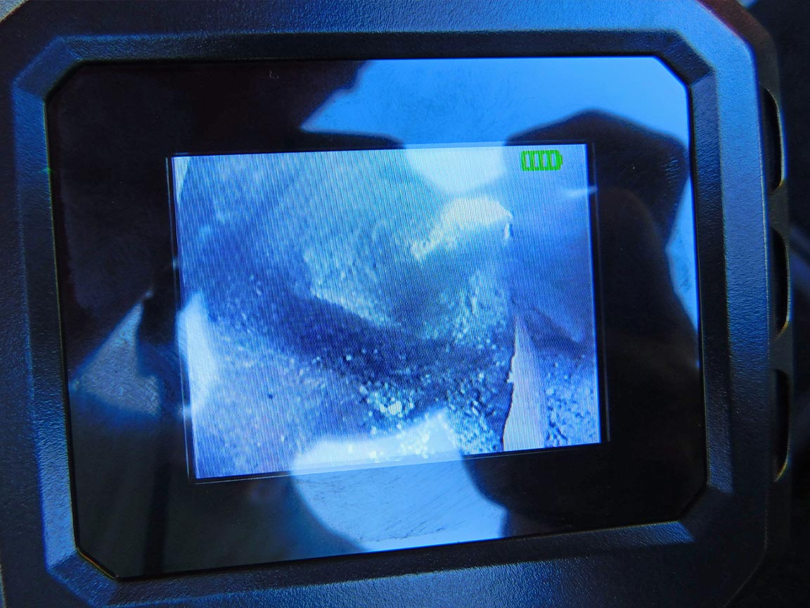
08: Alternatively, a scope can be borrowed from some major auto parts stores. A scope helps because there is no way to directly see the condition of the bolt, nut and cage. The deck lid spring and assembly need to be removed to replace the cage and nut. That is a subject for another tech article.
Step 9
09: The scope image is fuzzy like an underwater video but it shows that the cage is gone and that this nut and bolt are seriously rusted.
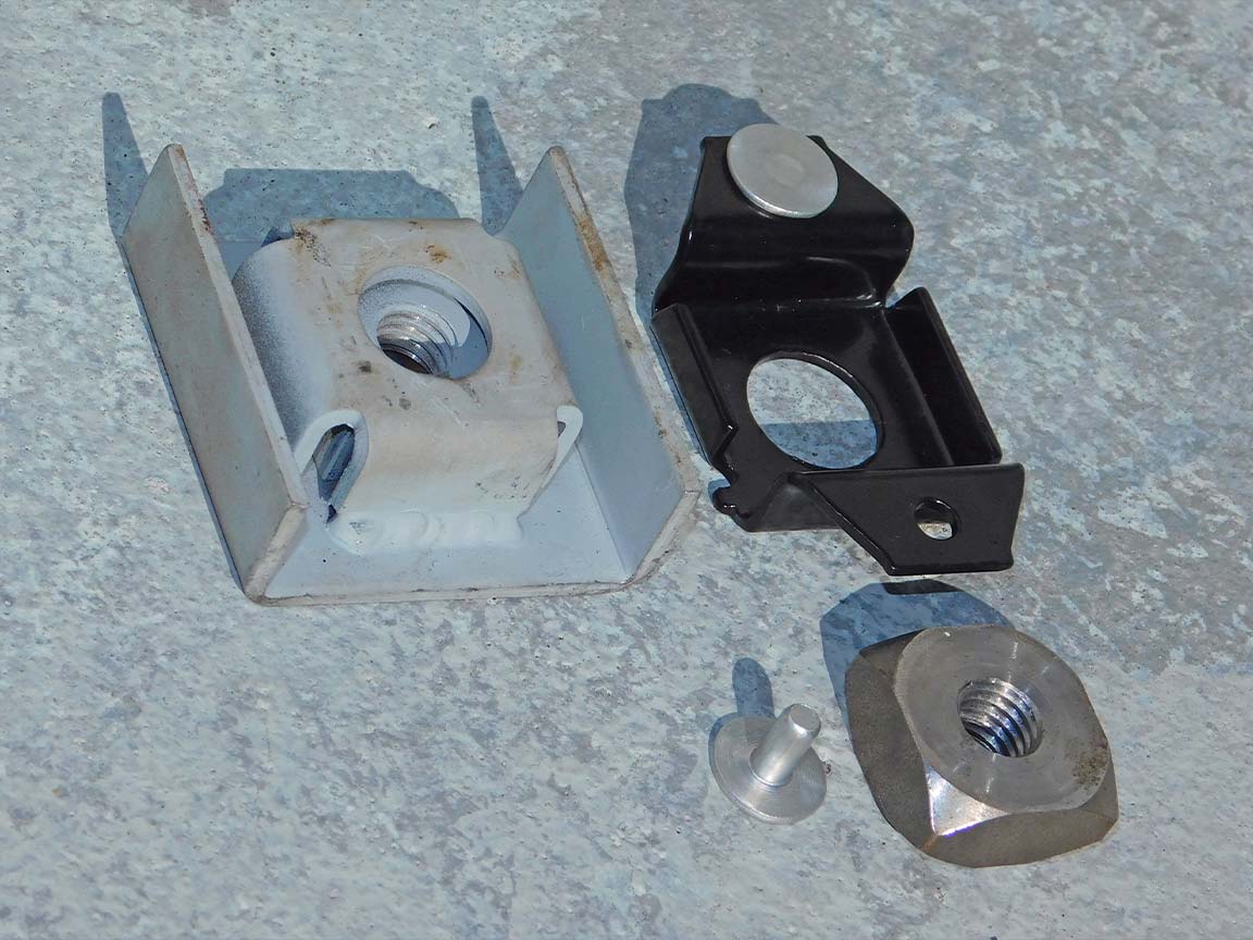
Step 10
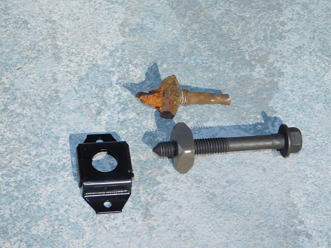
10: Zip Corvette offers both a replacement 1963-1982 #4 Body Mount Nut Cage and a replacement 1963-1982 Body Mount Square Nut. Zip Corvette also offers the 1968-1974E Body Mount Bracket (shown on the left) for the middle two mounts (#2 & #3). The #4 cage is much thinner and often weakened or destroyed by rusting. It is riveted to body support while the thicker Body Mount Bracket nut-cage assembly is welded to the frame.
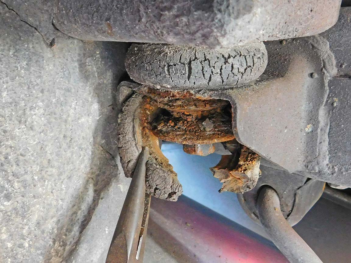
Step 11
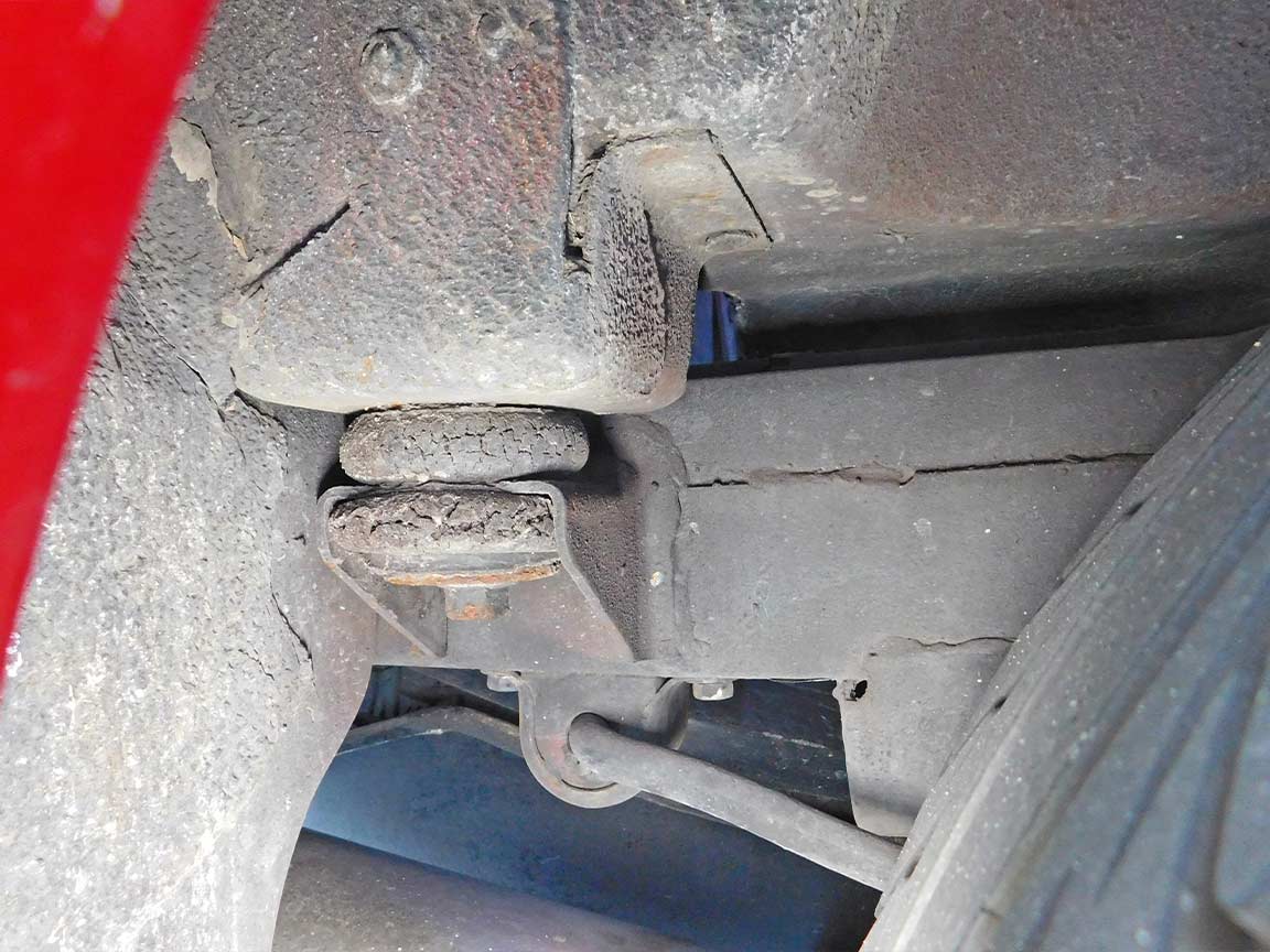
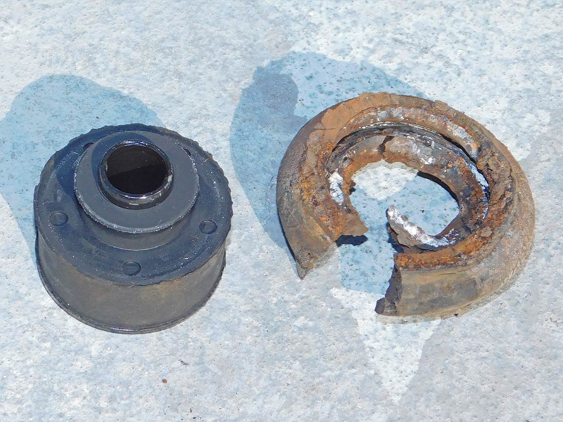
11: To remove a rust damaged rear bolt, first cut and peel away the lower rubber cushion. Note that deteriorated and cracked rubber mounts can hold water and catalyze corrosion in that area.
Step 12
12: Then use a hammer and chisel to knock off any layers of rust to make room for a saws-all or a cutoff wheel.
Step 13
13: Saw through the bolt with a saws-all using a fine-tooth metal cutting blade. Tip: shorten the blade by breaking off a few inches from its end.
Step 14
14: After removing the bolt head, tap the bolt upward completely through and out of the old rubber mount.
Step 15
15: A magnet can then be used to pull the remains of the bolt from the cavity. Vacuum any remaining rust particles from the cavity.
Step 16
16: The extremely rusted condition of the two original rear bolts and nuts shows that there was no way to remove them except by cutting the head off.
The new rubber body mount shows how deteriorated the old mounts are after almost 50 years on the car.
1963-1982 Corvette Body Mount Replacement Part 1
Source: Zip Corvette Parts 8067 Fast Lane | Mechanicsville, VA 23111 | (800) 962-9632
There’s an old saying journeymen car painters pass on to the new kids entering the trade, and that’s, if nothing else, make sure the driver door and the top of the hood look good. That’s a bit of advice I’d like to share with anyone that owns a 1984-’96 C4 Corvette. Whether you’re going to sell the car or you intend to cherish it forever, make sure the outer window seals are near mint or your C4 will be perceived to be in crummy overall condition.
A case in point is the triple-black 1990 Z51 Corvette featured in this article. I bought the car a year ago when I decided I needed a dependable economy car to take the monetary sting out of daily-driving my ’05 GMC Sierra. I found the 69,000-mile Z51 listed on Santa Barbara’s Craigslist 125 miles from my home; and the price was right. I had the seller email me a photo of the SPID (service parts identification sticker located inside console lid) and discovered the original owner checked all the right boxes when he ordered the car new from the dealer. I learned every performance option found on a 1990 RPO ZR1 or RPO B2K Callaway was on this car.
Anxious and armed with an envelope full of cash, I fled Orange County before sunrise. I’ll never forget my first impression of the black Z51 as I pulled into the driveway, it had a strong presence, as all Corvettes do, but its gap-toothed cracked outer window seals made it look bad. I took this as a summation of the car’s overall condition and I was beginning to lose interest fast. I wasn’t all that excited to test drive the Z51, but the owner insisted. I headed north from his beachfront home up the coast through the lush foliage of Hope Ranch and that was all it took to decide I was going to buy this car.
I’m not real adept when it comes time to chisel an owner down on the price of a used car, so it came in real handy that the two of us were standing next to the shabby window seals while we were discussing price. There’s no question in my mind the bad outer window seals undermined the seller’s perceived value of his car, and that’s the reason I got a good deal on a really great car.
Beyond cosmetic considerations, there’s numerous operational benefits to be gained by renewing a C4 Corvette’s outer window seals. The gaps left by missing chunks of rotted outer window seals allow dirt and water to enter inside the door’s workings, creating wind noise and potentially causing power window and electrical switch failures. Rusted window mechanisms can jam and prevent proper function.
For the person that likes to keep their Corvette nicely detailed plus add a few upgrades while they’re doing repair work, replacing the outer window seals presents a good opportunity to super detail the door panels, plus install sound and heat proofing.
2/32
01. Here’s what the factory original outer window seals looked like before replacement. Broken outer window seals allow water and dirt to enter inside the door and cause expensive electrical and/or mechanical damage.
3/32
02. The first step is to lower both side door windows and then disconnect the negative post of the battery.
4/32
03. The door panels must come off in order to replace the outer window seals. All Phillips screws that are visible in the door panels must be removed.
5/32
04. Notice how water entering and collecting inside the door caused the door panel screws to rust.
6/32
05. Tagging where the screws came from and storing them in a sealed bag is a good practice to ensure original hardware is not misplaced.
7/32
06. The power mirror control switch connector plug is released by unhooking (pull tab outward) at the switch.
8/32
07. To disconnect the power window switch, a special tool was homemade from a cotter key to release the two locking tabs simultaneously.
9/32
08. Twisting the special homemade tool upward opened the two locking tabs enough to separate the plug from the switch.
10/32
09. To remove the courtesy light from the door panel, there are two tabs on top of the light that need to be pressed down. Then the top of the light comes out first.
11/32
10. Behind the courtesy light is a Phillips screw that must be removed.
12/32
11. To access the Phillips screw behind the door lock knob, a hook tool is used to pull the lock knob forward.
13/32
12. The door lock knob pulls outward to release it from the lock rod.
14/32
13. The hook tool was used to pull the lock rod down and forward to allow access to remove the hidden Phillips screw.
15/32
14. The inside door handle is pulled outward (same as opening the door) to release the lock panel from the door panel.
16/32
15. The door lock panel pulls outward to remove, but does not need to be removed completely from the wiring.
17/32
16. The rear hatch switch (adjacent the inside door lock mechanism at rear) must be disconnected. Unplug by opening the locking tab.
18/32
17. To replace the outer window seals, this clear plastic liner does not need to be removed, but I chose to upgrade to the later year model C4 door panel insulators from Corvette Central (PN 284084).
19/32
18. The two clips holding the liner only need to come forward enough to unwrap the clear plastic liner from the clips.
20/32
19. While the clear plastic liner was removed, I used the access to blow out and vacuum dirt and broken chunks of the original outer seal left inside the door.
21/32
20. There are three pop rivets that must be drilled out to remove the old outer window seal. To gain access to the rivets, the door weatherstripping must be moved out of the way.
22/32
21. After removing the two 7mm-headed bolts and carefully peeling the weatherstrip back, blue tape was used to hold the weatherstrip clear of the drill.
23/32
22. Notice how nicely the new Corvette Central door panel insulator conforms to the door with heavier material.
24/32
23. To keep the Z51 factory correct, the original screws were wire-wheeled and painted with Eastwood semi-gloss Extreme Chassis Black satin spray paint.
25/32
24. For additional help keeping the triple-black ’90 Z51 cool and quiet, Dynamat was adhered inside the door panels and doors. Measure the area to be covered and cut it out with a razor blade or mat knife.
26/32
25. Use the minimum sized drill bit needed to drill out the rivets. Do not drill any deeper than necessary or a hole might be drilled clean through the door.
27/32
26. The window guides must move as far back as they can in order to move the window glass back towards the interior. Mark (scratch) the adjustment position of the two window guides before loosening (do not remove guides).
28/32
27. With the three rivets drilled out, the old outer window seal can be removed. Sometimes they fall right off and other times you’ll have to fight to remove. If it is difficult to spread the clip jaws, open to release the outer seal from the door. These fought. Careful not to bend the new outer window seal, start at the rear of the door angling the clips into their corresponding holes and push with a slight twist the new outer window seal into place.
29/32
28. Then it worked best to install the three rivets into the installed outer window seal.
30/32
29. The next step was to slip the pop rivet gun over the rivet and complete riveting.
31/32
30. Do not glue in place. Duct tape is reversible and worked well to hold the door panel insulator in position.
32/32
31. Reverse disassembly to install door panels. The door panel was placed over inside the door and pressed from the top down into its place. The electrical connectors (plugs) were attached and the Phillips screws were reinstalled. Mothers’ products were used to clean and detail during and after assembly.
The C4 No Flex kit from Vette2Vette looks simple enough that an offshore knock-off artist could reproduce a reasonable facsimile, but a counterfeit kit couldn’t be installed as easy, or work as well. An observation we formed after this installation was completed and the car road tested. The C4 No Flex kit installed easily with every bolthole lining up perfectly and the mounting brackets fit right into place. There was not one snag from start to finish.
But before clarifying why a cheap knock-off wouldn’t be as good, allow us to explain what motivated the upgrade. The C4 is recognized as the first modern Corvette, yet it still has traces of its primitive forebears. The C4 was a respectable transition series into the modern Corvettes that followed, but the C4 did have growing pains. Amongst C4 owner’s complaints were the squeaks, creaks and darting over road irregularities brought on by its Targa top, as opposed to the more rigidly enforced T-top of the C3.
Dave McLellan, Corvette Chief Engineer from 1975-’92, was quoted as saying his design staff originally intended the C4 as a T-top car with a “T-bar roof connection as a structural member.” Then, future GM President Lloyd Reuss (1990-’92) specified the C4 should have a Targa top. Reportedly, this directive came down late in the production cycle and meant the C4 was released with a frame that liked to flex in the middle. (It’s interesting to note that Reuss was instrumental in returning a Corvette soft-top convertible to the 1986 model year lineup.)
The good news for 1986-’96 C4 owners is there’s a direct bolt-in aftermarket solution designed by Gordon Killebrew; Vette2Vette products calls it their C4 No Flex kit. It’s a frame stiffener bar system that puts the framerails in compression, not allowing the framerails to flex under load. In 1986, when the soft-top convertible was added to the lineup, Corvette engineers devised an X-brace to beef-up the framerails. A major drawback of the factory X-brace is it hangs lower and requires removal to access the underside of the drivetrain.
The subject vehicle is my triple-black 1990 Z51 with a little over 75,000 miles. I bought the car in Santa Barbara, California, from a guy that lived right on the beach. He bought an old Porsche and let the Corvette sit in his driveway for a few years. The ’90 C4 looked pretty rough, deteriorating rubber and cracked fiberglass from hit-and-runs perpetrated by fellow Santa Barbarians. I didn’t care to take it out for a test-drive because I was going to pass on the deal but the seller insisted. That drive changed everything. The car drove incredibly tight, just like a brand-new 1990 Corvette, including the expected squeaks, rattles, and creaks. My last Corvette was a much more primitive 1959, so I didn’t really mind, but as time has passed I’ve decided to upgrade the Z51 to behave as civilized as possible.
The results after installing Vette2Vette’s C4 No Flex kit were immediate. The irritating noises the car had driving over the speed bumps pulling into Vette’s tech center were completely gone, and the gains in handling are readily apparent when accelerating hard into the turns. Vette2Vette stands behind its C4 No Flex kit saying, “We guarantee that you will like our product. If not we will refund your money.”
2/20
1. Every nut and bolt necessary, plus the Heim joints, to install the C4 No Flex kit from Vette2Vette is included. Important! The C4 No Flex kit should be installed with the weight of the car on the wheels.
3/20
2. Ready to install right from the box, the mounting brackets and bars arrive powdercoated in a deep gloss black finish.
4/20
3. It’s a good practice to ensure the threads aren’t buggered and are free from excessive rust. Our first step was to spray penetrating oil into the boltholes.
5/20
4. Followed by chasing the threads with the correlating mounting bolt. If excessive force is needed, stop and chase the threads with a tap.
6/20
5. As a starting point to mount the bars, thread (screw) the Heim joints into the bar halfway. Note, there is a righthand and lefthand threaded Heim joint for each bar.
7/20
6. Mount the front brackets to the existing 1986-’96 convertible X-brace mounting holes. Torque the mounting bolts to 46 ft-lb.
8/20
7. The rear C4 No Flex kit mounting brackets install beneath the spindle rod brackets (suspension links).
9/20
8. Install the rear mounting brackets by removing the lower bolts (one per side) from the spindle rod brackets.
10/20
9. Note, the driver-side emergency brake cable needs to be unbolted and temporarily moved out of the way for the C4 No Flex kit mounting bracket to fit.
11/20
10. Bolt the C4 No Flex mounting bracket in place but only tighten the bolt just enough to hold it in place and parallel (align) to the framerail.
12/20
11. Then, use a 27/64-inch transfer center punch in the bracket hole to mark where a 7/16-inch hole must be drilled. Remove the bracket and drill the hole.
13/20
12. Reinstall the bracket and torque the 3/8-inch diameter bolt to 50 ft-lb and the lower spindle rod bracket bolt to 80 ft-lb.
14/20
13. Raise the rods into place and turn Heim joint inward or outward to align the Heim joint hole with the mounting bracket hole in order to insert 5/8-11 bolts.
15/20
14. Once the rods are centered with an equal length of thread exposed on the front and rear Heim joints torque the 5/8-11 bolts to 80 ft-lb.
16/20
15. Marking with a piece of blue masking tape made it easy to keep count how many revolutions the bar was turned to increase the load (tension) on the C4 No Flex kit.
17/20
16. Twisting (tightening) the bar by hand works at first but a 23mm open-end wrench must be used on the flats to tighten to full tension.
18/20
17. To adjust to one’s personal ride preference, remove the Targa top and measure from the windshield header to the halo. Next, jack the car up with the wheels suspended in air and take the same measurement. When the C4 No Flex kit is properly adjusted these measurements will be the same. Once that is the case, lock the Heim joints in place.
19/20
18. In this instance, the emergency brake cable (driver-side rear bracket) maintained a more graceful bend by not reattaching to the stock support bracket.
20/20
19. After Vette2Vette’s C4 No Flex kit was installed the hood and doors could be opened or closed with the car jacked up, and with or without Targa top installed.